Inside the Machine: An Illustrated Introduction to Microprocessors and Computer Architecture (80 page)
Authors: jon stokes
Tags: #Computers, #Systems Architecture, #General, #Microprocessors

z
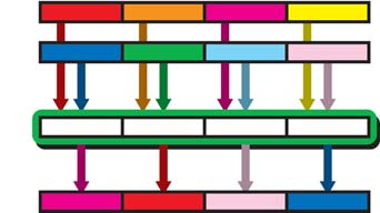
4 elements, where each element is either a 32-bit signed or unsigned
integer, or a single-precision (32-bit) IEEE floating-point number.
Figure 8-3 can help you visualize how these elements are packed
together.
16 × 8 Bits
8 × 16 Bits
4 × 32 Bits
Figure 8-3: Vectors as packed data formats
AltiVec Vector Operations
Motorola’s AltiVec literature divides the types of vector operations that
AltiVec can perform into four useful and easily comprehensible categories.
Because these categories offer a good way of dividing up the basic things you
can do with vectors, I’ll use Motorola’s categories to break down the major
types of vector operations. I’ll also use pictures similar to those from Motorola’s AltiVec literature, modifying them a bit when needed.
Before looking at the types of operations, note that AltiVec’s instruction
format supports up to four operands, laid out as follows:
AltiVec_instruction source1, source2, filter/mod, destination
170
Chapter 8
itm08_03.fm Page 171 Thursday, January 11, 2007 10:28 AM
The main difference to be noted is the presence of the
filter/mod
operand, also called a
control operand
or
control vector
. This operand specifies a register that holds either a bit mask or a control vector that somehow
modifies or sets the terms of the operation. You’ll see the control vector in
action when we look at the vector permute.
AltiVec’s four-operand format is much more flexible than the two-
operand format available to Intel’s SIMD instructions, making AltiVec a
much more ideal vector processing instruction set than the Pentium line’s
SSE or SSE2 extensions. The
x
86 ISA’s SIMD extensions are limited by their two-operand format in much the same way that the
x
86 floating-point
extension is limited by its stack-based register file.
Motorola’s categories for the vector operations that the AltiVec can
perform are as follows:
z
intra-element arithmetic
z
intra-element non-arithmetic
z
inter-element arithmetic
z
inter-element non-arithmetic
Intra-Element Arithmetic and Non-Arithmetic Instructions
Intra-element arithmetic operation
is one of the most basic and easy-to-grasp categories of vector operation because it closely parallels scalar arithmetic.
Consider, for example, an intra-element addition. This involves lining up
two or three vectors (VA, VB, and VC) and adding their individual elements
together to produce a sum vector (VT). Figure 8-4 contains an example of
intra-element arithmetic operation at work on three vectors, each of which
consists of four 32-bit numbers. Other intra-element operations include
multiplication, multiply-add, average, and minimum.
Intra-element non-arithmetic operations
basically work the same way as intra-element arithmetic functions, except for the fact that the operations per-
formed are different. Intra-element non-arithmetic operations include
logical operations like AND, OR, and XOR.
Figure 8-4 shows an intra-element addition involving three vectors of
pixel values: red, blue, and green. The individual elements of the three
vectors are added to produce a target vector consisting of white pixels.
VA
VB
VC
+
+
+
+
VT
Figure 8-4: Intra-element arithmetic operations
Intel’s Pentium 4 vs. Motorola’s G4e: The Back End
171
The following list summarizes the types of vector intra-element instruc-
tions that AltiVec supports:
z
integer logical instructions
z
integer arithmetic instructions
z
integer compare instructions
z
integer rotate and shift instructions
z
floating-point arithmetic instructions
z
floating-point rounding and conversion instructions
z
floating-point compare instructions
z
floating-point estimate instructions
z
memory access instructions
Inter-Element Arithmetic and Non-Arithmetic Instructions
Inter-element arithmetic operations
are operations that happen between the elements in a single vector. An example of an inter-element arithmetic
operation is shown in Figure 8-5, in which the elements in one vector are
added together and the total is stored in an accumulation vector—VT.
VA
+
VT
Figure 8-5: An inter-element sum across operation
Inter-element non-arithmetic operations
are operations like vector permute, which rearrange the order of the elements in an individual vector. Figure 8-6
shows a vector permute instruction. VA and VB are the source registers that
hold the two vectors to be permuted, VC contains the control vector that tells
AltiVec which elements it should put where, and VT is the destination register.
VA
VB
VC
VA[3]
VA[1]
VB[4]
VB[1]
VT
Figure 8-6: An inter-element permute operation
172
Chapter 8
The following list summarizes the types of vector inter-element instruc-
tions that AltiVec supports:
z
Alignment support instructions
z
Permutation and formatting instructions
z
Pack instructions
z
Unpack instructions
z
Merge instructions
z
Splat instructions
z
Shift left/right instructions
The G4e’s VU: SIMD Done Right
The AltiVec extension to PowerPC adds 162 new instructions to the PowerPC
instruction set. When Motorola first implemented AltiVec support in their
PowerPC processor line with the MPC 7400, they added 32 new AltiVec
registers to the G4’s die, along with two dedicated AltiVec SIMD functional
units. All of the AltiVec calculations were done by one of two fully-pipelined,
independent AltiVec execution units.
The G4e improves significantly on the original G4’s AltiVec implemen-
tation. The processor boasts four independent AltiVec units, three of which
are fully pipelined and can operate on multiple instructions at once. These
units are as follows:
Vector permute unit
This unit handles the instructions that rearrange the operands within a
vector. Some examples are permute, merge, splat, pack, and unpack.
Vector simple integer unit
This unit handles all of the fast and simple vector integer instructions.
It’s basically just like one of the G4e’s three fast IUs, except vectorized.
This unit has only one pipeline stage, so most of the instructions it exe-
cutes are single-cycle.
Vector complex integer unit
This is the vector equivalent of the G4e’s one slow IU. It handles the
slower vector instructions, like multiply, multiply-add, and so on.
Vector floating-point unit
This unit handles all vector floating-point instructions.
The G4e can issue up to two AltiVec instructions per clock cycle, with
each instruction going to any one of the four vector execution units. All of
the units, with the exception of the VSIU, are pipelined and can operate on
multiple instructions at once.
All of this SIMD execution hardware is tied to a generous register file
that consists of 32 128-bit architectural registers and 16 additional vector
rename registers.
Intel’s Pentium 4 vs. Motorola’s G4e: The Back End
173
Intel’s MMX
The story of MMX and SSE/KNI/MMX2 is quite a bit more complicated
than that of AltiVec, and there are a number of reasons why this is so.
To begin with, Intel first introduced MMX as an
integer-only
SIMD solution, so MMX doesn’t support floating-point arithmetic at all. Another weakness
of MMX is the fact that Intel jumped through some hoops to avoid adding
a new processor state, hoops that complicated the implementation of MMX.
I’ll deal with this in more detail
in “SSE and SSE2” on page 175.
Where AltiVec’s vectors are 128 bits wide, MMX’s are only 64 bits wide.
These 64-bit vectors can be subdivided into:
z
8 elements (a packed byte), where each element is an 8-bit integer;
z
4 elements (a packed word), where each element is a 16-bit signed or
unsigned integer;
z
2 elements (packed double word), where each element is a 32-bit signed
or unsigned integer.
These vectors are stored in eight MMX registers, based on a flat-file
model. These eight registers, MM0 to MM7, are
aliased
onto the
x
87’s stack-based floating-point registers, FP0 to FP7. Intel did this in order to avoid
imposing a costly
processor state switch
any time you want to use MMX instructions. The drawback to this approach is that floating-point operations and
MMX operations must share a register space, so a programmer can’t mix
floating-point and MMX instructions in the same routine. Of course, since
there’s no
mode bit
for toggling the register file between MMX and floating-point usage, there’s nothing to prevent a programmer from pulling such a
stunt and corrupting his floating-point data by overwriting it with integer
vector data.
The fact that a programmer can’t mix floating-point and MMX instruc-
tions normally isn’t a problem, though. In most programs, floating-point
calculations are used for generating data, while SIMD calculations are used
for displaying it.
In all, MMX added 57 new instructions to the
x
86 ISA. The MMX instruc-
tion format is pretty much like the conventional
x
86 instruction format:
MMX_instruction mmreg1, mmreg2
In this instruction,
mmreg1
is the both the destination and source operand, meaning that
mmreg1
gets overwritten by the result of the calculation. For the reasons outlined in the previous discussion of operand formats, this two-operand instruction format isn’t nearly as optimal as AltiVec’s four-operand
format. Furthermore, MMX instructions lack that third filter/mod vector
that AltiVec has. This means that you can’t do those one-cycle, arbitrary two-
vector permutes.
174
Chapter 8
SSE and SSE2
Even as MMX was being rolled out, Intel knew that its 64-bit nature and
integer-only limitation made it seriously deficient as a vector processing
solution. An article in an issue of the
Intel Technology Journal
tells this story: In February 1996, the product definition team at Intel presented
Intel’s executive staff with a proposal for a single-instruction-
multiple-data (SIMD) floating-point model as an extension to IA-
32 architecture. In other words, the “Katmai” processor, later to be
externally named the Pentium III processor, was being proposed.
The meeting was inconclusive. At that time, the Pentium®
processor with MMX instructions had not been introduced and
hence was unproven in the market. Here the executive staff were
being asked essentially to “double down” their bets on MMX
instructions and then on SIMD floating-point extensions. Intel’s
executive staff gave the product team additional questions to
answer and two weeks later, still in February 1996, they gave the
OK for the “Katmai” processor project. During the later definition
phase, the technology focus was refined beyond 3D to include
other application areas such as audio, video, speech recognition,
and even server application performance. In February 1999, the
Pentium III processor was introduced.
—
Intel Technology Journal, Second Quarter, 1999
Intel’s goal with SSE (Streaming SIMD Extensions, aka MMX2/KNI) was
to add four-way, 128-bit SIMD single-precision floating-point computation to
the
x
86 ISA. Intel went ahead and added an extra eight 128-bit architectural registers, called
XMM registers
, for holding vector floating-point instructions.
These eight registers are in addition to the eight MMX/
x
87 registers that were already there. Since these registers are totally new and independent,