Make: Electronics (78 page)
Authors: Charles Platt

Framing Your Cart
For reasons that will soon be apparent, I’ve chosen an unusual diamond-shaped configuration of wheels. In the rendering shown in Figure 5-91, the front wheel (at the far end of the cart) applies power, the rear wheel (at the near end of the cart) steers the cart when backing up, and the side wheels prevent it from falling over.
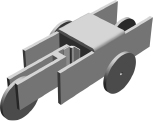
Figure 5-91.
If you have 3D rendering software, it can be a great way to test the feasibility of a construction project before you start cutting materials and trying to fit pieces together. This rendering was a proof-of-concept for the Little Robot Cart.
Depending on the type of motor that you buy, you’ll have to improvise a way to mount it in the front section of the cart. Don’t be afraid to use kludges such as cable ties, duct tape, or even rubber bands to attach the motor to the frame. We’re making a rough prototype, here, not a thing of beauty (although if you decide you like the cart, you can always rebuild it beautifully later).
The plan in Figure 5-92 shows the pieces that you will need. Part A is the body of the cart. If you’re going to bend it from ABS, you should drill half-inch holes, with a forstner bit, at the four inside corners, so that these corners have rounded edges. If you simply saw the plastic to make sharp 90° corners, the plastic may develop fissures at the corners when you bend it. If you don’t have a plastic bender and don’t feel inclined to buy one, you can make Part A from three separate rectangles and then screw them together.
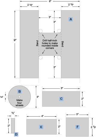
Figure 5-92.
These sections of 1/4-inch plastic can be assembled to create the simple cart described in
Experiment 32
.
Part B is a wheel, of which you will need four. I cut them using a 3-inch hole saw. The front wheel is screwed to whatever disc or arm you obtained to mate with the shaft of your motor. See Figure 5-93.
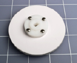
Figure 5-93.
A 3-inch wheel is screwed to the disc that mates with the drive shaft of the motor.
Parts C, D, and E assemble to form a yoke in which the rear wheel is mounted. I used a 2-inch hinge to pivot the yoke. The hinge is mounted on Part F, which is a partition located midway in the frame of the cart. The photographs in Figures 5-94 and 5-95 will help to make this clear. Initially, when you install Part F, use only two screws, one each side, so that you can adjust its angle a little. This will be necessary to optimize the contact of the wheels with the floor.
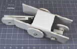
Figure 5-94.
The assembled body of the cart, before adding control electronics. The wheel at the righthand end will pull the cart from left to right. The hinged trailing wheel will allow the cart to move in a relatively straight line when it moves forward, but will tend to turn it when it backs up.
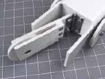
Figure 5-95.
A closeup of the hinged trailing wheel, which rotates freely and can flip from side to side with minimal friction.
The side wheels and rear wheel must spin freely, but on the other hand, they shouldn’t wobble. I simply tightened the nuts on the bolts that serve as axles for the wheels, until there was maybe half a millimeter of clearance. I added a drop of Loctite to stop the nuts from getting loose.
The plans don’t show precisely where to drill holes for the axle bolts, because the location will depend on the size of your wheels. You can figure this out as you go along. Just make sure that the side wheels aren’t mounted too low. We don’t want them to lift the front wheel or the rear wheel off the floor. If the side wheels are a fraction higher off the ground than the front and rear wheels, that’s good.
If you have tile or wood floors, your cart may acquire better traction if you wrap a thick rubber band around each disc that you use for the drive wheel and the steering wheel.
The most important aspect of the construction is to place microswitches where they’ll be triggered when the cart runs into something. I placed mine at the front corners, as shown in Figures 5-96 and 5-97. And that brings me to the electronics.
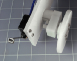
Figure 5-96
.
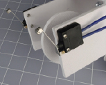
Figure 5-97.
Two microswitches with metal arms are mounted on each side of the cart, where they will sense any obstacle.
The Circuit
The schematic is very, very simple, with only four principal components: two microswitches that sense obstacles in front of the cart, one relay, and one 555 timer. You will also need a small power switch, a battery or battery pack, and a resistor, and capacitors to go with the timer. A trimmer potentiometer will allow you to adjust the “on” time of the 555 timer, which will determine how long the cart takes to back up. See Figure 5-98.
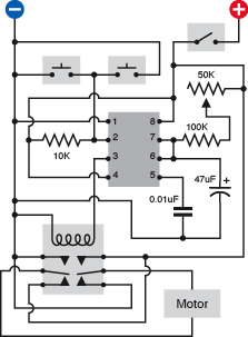
Figure 5-98.
This ultrasimple schematic is all the cart needs to enable it to back up when it hits an obstacle.
The motor I chose requires 5 volts, so I had to use a voltage regulator with a 9-volt battery. If your motor uses 6 volts, you can wire four AA batteries to it directly. If you have a 12-volt motor, you can use two 9-volt batteries in series, supplying power through a 12-volt voltage regulator.
Assemble the components, mount them on the cart, and switch it on, and it should move forward slowly in a more-or-less straight line. If it moves backward, reverse your connection to the terminals on the motor.
When the cart bumps into something, either of the microswitches will connect negative voltage to the input pin of the 555 timer. This triggers the timer, which runs in monostable mode, generating a single pulse lasting about 5 seconds, which closes the relay, which is wired so that it reverses the voltage to the motor.
When the voltage is reversed to a simple DC motor, it runs backward. So the cart backs up. Because the rear wheel is mounted in a yoke that pivots, the yoke will tend to flip one way or the other, causing the cart to describe an arc as it moves backward. At the end of the timer cycle, the relay relaxes and the cart starts moving forward again. In forward mode, the rear wheel just follows along without applying any steering force, so the cart tends to follow a straight line—until it hits another obstacle, at which point it backs up, and tries another path.