Read The Design of Everyday Things Online
Authors: Don Norman
The Design of Everyday Things (26 page)

FIGURE 4.4.
  Â
Incomprehensible Light Switches.
Banks of switches like this are not uncommon in homes. There is no obvious mapping between the switches and the lights being controlled. I once had a similar panel in my home, although with only six switches. Even after years of living in the house, I could never remember which to use, so I simply put all the switches either up (on) or down (off). How did I solve the problem? See
Figure 4.5
.
I once lived in a wonderful house on the cliffs of Del Mar, California, designed for us by two young, award-winning architects. The house was wonderful, and the architects proved their worth by the spectacular placement of the house and the broad windows that overlooked the ocean. But they liked spare, neat, modern design to a fault. Inside the house were, among other things, neat rows of
light switches: A horizontal row of four identical switches in the front hall, a vertical column of six identical switches in the living room. “You will get used to it,” the architects assured us when we complained. We never did.
Figure 4.4
shows an eight-switch bank that I found in a home I was visiting. Who could remember what each does? My home only had six switches, and that was bad enough. (Photographs of the switch plate from my Del Mar home are no longer available.)
The lack of clear communication among the people and organizations constructing parts of a system is perhaps the most common cause of complicated, confusing designs. A usable design starts with careful observations of how the tasks being supported are actually performed, followed by a design process that results in a good fit to the actual ways the tasks get performed. The technical name for this method is
task analysis
. The name for the entire process is
human-centered design
(HCD), discussed in
Chapter 6
.
The solutions to the problem posed by my Del Mar home require the natural mappings described in
Chapter 3
. With six light switches mounted in a one-dimensional array, vertically on the wall, there is no way they can map naturally to the two-dimensional, horizontal placement of the lights in the ceiling. Why place the switches flat against the wall? Why not redo things? Why not place the switches horizontally, in exact analogy to the things being controlled, with a two-dimensional layout so that the switches can be placed on a floor plan of the building in exact correspondence to the areas that they control? Match the layout of the lights with the layout of the switches: the principle of natural mapping. You can see the result in
Figure 4.5.
We mounted a floor plan of the living room on a plate and oriented it to match the room. Switches were placed on the floor plan so that each switch was located in the area controlled
by that switch. The plate was mounted with a slight tilt from the horizontal to make it easy to see and to make the mapping clear: had the plate been vertical, the mapping would still be ambiguous. The plate was tilted rather than horizontal to discourage people (us or visitors) from placing objects, such as cups, on the plate: an example of an anti-affordance. (We further simplified operations by moving the sixth switch to a different location where its meaning was clear and it did not confuse, because it stood alone.)
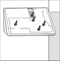
FIGURE 4.5.
  Â
A Natural Mapping of Light Switches to Lights.
This is how I mapped five switches to the lights in my living room. I placed small toggle switches that fit onto a plan of the home's living room, balcony, and hall, with each switch placed where the light was located. The X by the center switch indicates where this panel was located. The surface was tilted to make it easier to relate it to the horizontal arrangement of the lights, and the slope provided a natural anti-affordance, preventing people from putting coffee cups and drink containers on the controls.
It is unnecessarily difficult to implement this spatial mapping of switches to lights: the required parts are not available. I had to hire a skilled technician to construct the wall-mounted box and install the special switches and control equipment. Builders and electricians need standardized components. Today, the switch boxes that are available to electricians are organized as rectangular boxes meant to hold a long, linear string of switches and to be mounted horizontally or vertically on the wall. To produce the appropriate spatial array, we would need a two-dimensional structure that could be mounted parallel to the floor, where the switches would be mounted on the top of the box, on the horizontal surface. The switch box should have a matrix of supports so that there can be free, relatively unrestricted placement of the switches in whatever pattern best suits the room. Ideally the box would use small switches, perhaps low-voltage switches that would control a separately mounted control structure that takes care of the lights (which is what I did in my home). Switches and lights could communicate
wirelessly instead of through the traditional home wiring cables. Instead of the standardized light plates for today's large, bulky switches, the plates should be designed for small holes appropriate to the small switches, combined with a way of inserting a floor plan on to the switch cover.
My suggestion requires that the switch box stick out from the wall, whereas today's boxes are mounted so that the switches are flush with the wall. But these new switch boxes wouldn't have to stick out. They could be placed in indented openings in the walls: just as there is room inside the wall for the existing switch boxes, there is also room for an indented horizontal surface. Or the switches could be mounted on a little pedestal.
As a side note, in the decades that have passed since the first edition of this book was published, the section on natural mappings and the difficulties with light switches has received a very popular reception. Nonetheless, there are no commercial tools available to make it easy to implement these ideas in the home. I once tried to convince the CEO of the company whose smart home devices I had used to implement the controls of
Figure 4.5
, to use the idea. “Why not manufacture the components to make it easy for people to do this,” I suggested. I failed.
Someday, we will get rid of the hard-wired switches, which require excessive runs of electrical cable, add to the cost and difficulties of home construction, and make remodeling of electrical circuits extremely difficult and time consuming. Instead, we will use Internet or wireless signals to connect switches to the devices to be controlled. In this way, controls could be located anywhere. They could be reconfigured or moved. We could have multiple controls for the same item, some in our phones or other portable devices. I can control my home thermostat from anywhere in the world: why can't I do the same with my lights? Some of the necessary technology does exist today in specialty shops and custom builders, but they will not come into widespread usage until major manufacturers make the necessary components and traditional electricians become comfortable with installing them. The tools for creating switch configurations that use good mapping principles
could become standard and easy to apply. It will happen, but it may take considerable time.
Alas, like many things that change, new technologies will bring virtues and deficits. The controls are apt to be through touch-sensitive screens, allowing excellent natural mapping to the spatial layouts involved, but lacking the physical affordances of physical switches. They can't be operated with the side of the arm or the elbow while trying to enter a room, hands loaded with packages or cups of coffee. Touch screens are fine if the hands are free. Perhaps cameras that recognize gestures will do the job.
ACTIVITY-CENTERED CONTROLS
Spatial mapping of switches is not always appropriate. In many cases it is better to have switches that control activities: activity-centered control. Many auditoriums in schools and companies have computer-based controls, with switches labeled with such phrases as “video,” “computer,” “full lights,” and “lecture.” When carefully designed, with a good, detailed analysis of the activities to be supported, the mapping of controls to activities works extremely well: video requires a dark auditorium plus control of sound level and controls to start, pause, and stop the presentation. Projected images require a dark screen area with enough light in the auditorium so people can take notes. Lectures require some stage lights so the speaker can be seen. Activity-based controls are excellent in theory, but the practice is difficult to get right. When it is done badly, it creates difficulties.
A related but wrong approach is to be device-centered rather than activity-centered. When they are device-centered, different control screens cover lights, sound, computer, and video projection. This requires the lecturer to go to one screen to adjust the light, a different screen to adjust sound levels, and yet a different screen to advance or control the images. It is a horrible cognitive interruption to the flow of the talk to go back and forth among the screens, perhaps to pause the video in order to make a comment or answer a question. Activity-centered controls anticipate this need and put light, sound level, and projection controls all in one location.
I once used an activity-centered control, setting it to present my photographs to the audience. All worked well until I was asked a question. I paused to answer it, but wanted to raise the room lights so I could see the audience. No, the activity of giving a talk with visually presented images meant that room lights were fixed at a dim setting. When I tried to increase the light intensity, this took me out of “giving a talk” activity, so I did get the light to where I wanted it, but the projection screen also went up into the ceiling and the projector was turned off. The difficulty with activity-based controllers is handling the exceptional cases, the ones not thought about during design.
Activity-centered controls are the proper way to go, if the activities are carefully selected to match actual requirements. But even in these cases, manual controls will still be required because there will always be some new, unexpected demand that requires idiosyncratic settings. As my example demonstrates, invoking the manual settings should not cause the current activity to be canceled.
Constraints That Force the Desired Behavior
FORCING FUNCTIONS
Forcing functions are a form of physical constraint: situations in which the actions are constrained so that failure at one stage prevents the next step from happening. Starting a car has a forcing function associated with itâthe driver must have some physical object that signifies permission to use the car. In the past, it was a physical key to unlock the car doors and also to be placed into the ignition switch, which allowed the key to turn on the electrical system and, if rotated to its extreme position, to activate the engine.
Today's cars have many means of verifying permission. Some still require a key, but it can stay in one's pocket or carrying case. More and more, the key is not required and is replaced by a card, phone, or some physical token that can communicate with the car. As long as only authorized people have the card (which is, of course, the same for keys), everything works fine. Electric or hybrid vehicles
do not need to start the engines prior to moving the car, but the procedures are still similar: drivers must authenticate themselves by having a physical item in their possession. Because the vehicle won't start without the authentication proved by possession of the key, it is a forcing function.
Forcing functions are the extreme case of strong constraints that can prevent inappropriate behavior. Not every situation allows such strong constraints to operate, but the general principle can be extended to a wide variety of situations. In the field of safety engineering, forcing functions show up under other names, in particular as specialized methods for the prevention of accidents. Three such methods are interlocks, lock-ins, and lockouts.
INTERLOCKS
An interlock forces operations to take place in proper sequence. Microwave ovens and devices with interior exposure to high voltage use interlocks as forcing functions to prevent people from opening the door of the oven or disassembling the devices without first turning off the electric power: the interlock disconnects the power the instant the door is opened or the back is removed. In automobiles with automatic transmissions, an interlock prevents the transmission from leaving the Park position unless the car's brake pedal is depressed.
Another form of interlock is the “dead man's switch” in numerous safety settings, especially for the operators of trains, lawn mowers, chainsaws, and many recreational vehicles. In Britain, these are called the “driver's safety device.” Many require that the operator hold down a spring-loaded switch to enable operation of the equipment, so that if the operator dies (or loses control), the switch will be released, stopping the equipment. Because some operators bypassed the feature by tying down the control (or placing a heavy weight on foot-operated ones), various schemes have been developed to determine that the person is really alive and alert. Some require a midlevel of pressure; some, repeated depressions and releases. Some require responses to queries. But in all cases,
they are examples of safety-related interlocks to prevent operation when the operator is incapacitated.