125 Physics Projects for the Evil Genius (59 page)
Read 125 Physics Projects for the Evil Genius Online
Authors: Jerry Silver

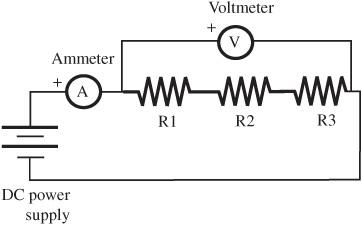
Figure 99-2
Schematic for measuring Ohm’s law
.
Voltage increases linearly with current. The slope of the line is the resistance the current is flowing through.
Ohm’s law is given by volts = resistance (ohms) × current (amps).
From this, you can see that the slope of the volts versus the current graph is resistance.
What happens if you have two or three resistors of the same resistance in a row, one connected to the next? This is called a
series circuit
and is shown in
Figure 99-3
. For a given voltage, is the current greater or less than for a single resistor?
What happens if you take those same three resistors and connect them in a parallel circuit, as shown in
Figure 99-4
?
Ohm’s law relates the voltage, current, and resistance of a circuit. The voltage at any particular time equals the current times the resistance.

Figure 99-3
Measuring resistors in a series circuit
.

Figure 99-4
Measuring resistors in a parallel circuit
.
Circuits: Bulbs and buzzers
.
If you have never built a circuit before with your own hands, this is your chance. Like many of the experiments in this book, various levels of complexity exist and you can take the experiment as far as you care to. You start with building a simple circuit, such as making a bell ring. Then, you build a basic telegraph system. You branch out and add series and parallel paths to simple circuits. Next, you measure the current and voltage at various points in the circuit. Finally, you look at how Ohm’s law can be applied to more complicated circuits.
- jumper wires
- 6 Christmas tree bulbs (or low-voltage bulbs and sockets)
- various (low-voltage) electrical devices such as bells, buzzers, LEDs
- DC power supply (or battery as in the previous project)
- knife switch
- ammeter (or multimeter set up as an ammeter)
- voltmeter (or multimeter set up as an voltmeter)
- for the telegraph: 5–10 feet of insulated wire, iron nail, two blocks of wood roughly 3 × 6 × ¾ inches, a second block of wood ¼ inch taller than the nail after being nailed into the block, a “tin” can, tin snips, and a few small nails
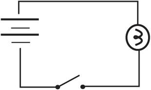
- Look at the circuit diagram in
Figure 100-1
and make the appropriate connections. - If you have an adjustable DC power supply, set a voltage of 2–3 volts and keep it constant throughout the test. You may need to adjust this, depending on the circuit you are working with.
- The circuit diagram should give you all the information you need. Here are a few details that may be helpful:
– Attach a jumper wire to the positive and negative terminals of the DC power supply or battery. (Not that the electrons care, but red is generally used for positive and black is used for negative for clarity in assembling the circuits.)
– There must be a complete path from the positive of the power supply and back to the negative.

Figure 100-1
Basic electrical circuit consisting of a battery, bulb and a switch
.
Making a telegraph– All connections must be metal-to-metal. If insulation is on the wires, you either need to use a bare-metal alligator connector or remove the insulation.
- Wind 25–50 turns of insulated wire around a large iron nail. Leave the two ends of the wire free and remove about ¾ inch of insulation.
- Hammer the nail into the wooden block.
- Cut two strips from your can, roughly 2½ inches long × ½ inch wide. Both pieces should be flexible.
- Attach one of the metal strips to the wooden block. The height of the wooden block should be ¼ inch higher than the nail.
- Attach the block with the metal strip to the base block, so the metal is above the head of the nail, but not touching.
- Build the “key” by nailing the second metal strip to the second block on one side, and then putting a nail underneath the other end of the metal strip. Leave enough of the nail head exposed above the wood surface, so you can wrap wire around it.
- OK. Let’s hook everything up. What you have is a series circuit from the DC power supply through the electromagnet to the key. The key is simply a switch. When it closes, the electromagnet pulls the metal strip down, as shown in
Figure 100-2
. Short and long durations are the dots and dashes of Morse code. If you have enough wire, you separate the key and the receiver by some distance. (Note: if you use this to cheat on tests in school, please make sure you don’t say you got the idea to do it here.)
- Attach each of the two ends of a Christmas tree bulb (or a low-voltage bulb in a socket) across the power supply. (This means one of the wires attached to the bulb goes to the positive terminal and the other end goes to the negative lead.)
- Connect three (or more) bulbs in series. Compare the brightness of these bulbs with the brightness of a single bulb.
- Connect three bulbs in parallel and compare with the brightness of bulbs in a series and a single bulb.
1. Repeat the previous set of measurements, but this time, include an ammeter in series with the circuit and a voltmeter in parallel with the circuit, as shown in
Figure 100-2
. It helps with the comparison if you keep the voltage constant throughout these measurements and compare the current flowing in the circuits.
2. Compare the current flowing in each the situations.

Figure 100-2
In a telegraph an electromagnet is activated when a switch is closed to complete the circuit
.
Expected Results3. Apply Ohm’s law (in the form R = V/I) to find the resistance of each of the circuits you measured.
Current will flow in a circuit if a continuous path exists from the positive terminal of the power supply through all components of the circuit, and then back to the negative terminal of the power supply.
Components in series
reduce
the current that can flow by effectively adding resistance to the circuit.
Components in parallel result in
increased
current flowing through the circuit. The resistance of the overall circuit is reduced when components are added in parallel.
When components are added in series, the voltage is distributed over all the components. As a result, less current is able to flow.
When components are added in parallel, alternate paths are provided for the current to flow back to the battery. For a given voltage, the push from the battery is able to force more current through the larger number of paths.
A next logical step is to create and test more complex networks of resistors. The following shows some examples. These can be analyzed using the following principles:
- Resistors in series simply add: R
series
= R
1
+ R
2 - Resistors in parallel add in a more complex fashion. Resistors in parallel can be thought of as one single equivalent resistance given by: 1/R
parallel
= 1/R
1
+ 1/R
2
+ … - These circuits can then be simplified by combining series and parallel circuits, and then applying Ohm’s law in its various forms (V = RI, R = VI, and I = V/R).
Ohm’s law determines how much current (or amps) flows through a circuit. For a given resistance (ohms), the greater the voltage, the greater the current.
How does heat affect resistance
?
When matter heats up, the atoms start moving faster, like cars in rush-hour traffic. The hotter it gets, the more difficult it is for electrons to make it through a wire. In this experiment, you explore what happens when a conductor gets hot.
- one 10-ohm resistor rated for 1 W or greater
- DC power supply or battery
- (optional) digital temperature sensor (some multimeters come with a thermocouple and setting to read the temperature)
- stopwatch
- Set up the circuit, as shown in
Figure 101-1
. - Attach the temperature sensor to the resistor. (Not to worry. If you don’t have a thermocouple, there is still a way for you to do this.)
- Set a voltage of about 5 V.
- Measure the voltage, current, and temperature.
- Continue taking readings of voltage, current, and temperature at regular intervals. If you don’t have a temperature sensor, you can still proceed, taking note of the fact that the resistor is heating up qualitatively. A relationship between resistance and time (rather than temperature) can still be established.
- Use Ohm’s law to determine the resistance by dividing the voltage by the current (in amps).
- What happens to resistance as the resistor heats up?
The higher the temperature, the higher the resistance. Resistance increases linearly with temperature. See
Figure 101-2
, which shows the resistance of a 5 centimeter (0.05 m) section of 20AWG copper wire over a range of temperatures.