125 Physics Projects for the Evil Genius (66 page)
Read 125 Physics Projects for the Evil Genius Online
Authors: Jerry Silver


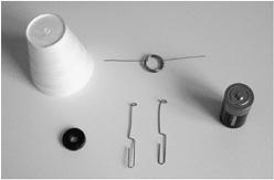
Figure 113-1
Parts to assemble a “no-frills” motor
.
- electrical tape
- optional: battery holder, Styrofoam cup
- Wind about 25–30 turns of the 22 gauge wire around a cylindrical coil form, such as a ballpoint pen or a small AAA battery.
- Leave a few of inches of wire free at each end.
- Pull the coil off the form you wound it around. Be careful and hold the wire, so it doesn’t spring out of shape (it doesn’t have to be perfect to work).
- Weave each of the ends of the wire around the coil a few times to hold the coil together. This becomes the armature of the motor. If you prefer, you can also use tape to help keep the coil together.
- The ends of the wire should be placed in a straight line to make a good axle. It can help if you double back, so the end sections consist of more than one thickness of wire. It also helps to overwrap the ends with the last segment of wire or tape.
- Using a utility knife, remove the insulation from the top half of the 22 gauge wire at both ends. You can also use sandpaper to do this. If the wire is coated with a colored layer, you can see when the insulation has been removed. If the wire is clear-coated, you must be more careful and keep track of where you are removing the insulation. Do not remove the insulation from the bottom half of the wire.
- When you finish, the side with the insulation removed must remain facing up on both ends.
- Make an armature support by first forming the paper clips into a loop. If you are using wire, remove insulation from each of two 1½-inch sections of wire and form a small circular loop about 1 millimeter in diameter in the center of each wire. A nail can serve as a good form to wrap the loop.
- Bend the wires to form a shape like a wishbone with the wire ends separated by a few millimeters.
- The two ends of the coils should easily fit into the armature supports and should be able to turn freely.
- Secure the armature support wires to the battery holder with tape.
- Establish electrical contact between the armature supports and the positive and negative terminals of the battery holder. You may need to use jumper wires to do this.
- Insert the ends of the armature (coil) into the holes of the armature supports. The armature supports should be spaced far enough apart so the coil is supported at both ends.
- Tape the battery to the top of the cup or insert the battery into the holder.
- Attach the magnet to the top of the battery holder just underneath the coil. Use tape or Velcro to do this. Make sure the coil can still spin easily and that it is just above the magnet. It may be necessary to raise or lower the armature supports to attain the correct height above the magnet.
- Spin the armature gently to get the motor started. If it doesn’t start spinning, try spinning it in the other direction. It will only spin in one direction.
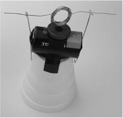
This may sound like a lot of steps, but it is very simple, as shown by
Figure 113-2
, which shows what this motor looks like when it is all assembled.

Figure 113-2
Basic DC motor
.
The motor should keep turning in one direction.
If it does not run, check all electrical connections. Be sure one support touches the negative end of the battery and the other support touches the positive end. Be sure the armature can spin freely. It is essential that the insulation be removed from only one-half of the turns and the uninsulated side of the wire is facing the same direction.
The basic concept of a motor is the repulsion of two magnetic fields, resulting in a repetitive turning motion. One magnet is a permanent magnet. The other is an electromagnet formed by a coil of wire through which an electrical current is flowing. The trick is only to have the magnetic fields repel, but not attract. If we had taken the insulation off the top and bottom sides of the enamel-coated wire used for the coil, the motor would go no more than one-half turn, and then stop as the coil and permanent magnet attracted each other. By leaving the insulation on the bottom
halves of the coil wires, no current flows through the circuit at a time when the magnets would attract. In our case, the momentum of the coil keeps it rotating until the uninsulated wires emerge just in time for the permanent magnet to repel the coil and rotate through another cycle. Other motor designs have what is called a
split commutator
, which goes one step better by changing the direction of the current flowing through the wire, so the magnets are always repulsive.
Double the spinning power by constructing a split-ring commutator. Try this by making the following modifications to the simple motor concept previously described:
- Insulate the
top
half of the loop of one armature support and insulate the
bottom
half of the other armature loop. - Starting with insulated enamel-coated ends of the 22 gauge wire, remove the insulation from the
top
on one side and the
bottom
on the other side. - Once you start the motor, the contacts have been set up to make sure current flows through the coil at a time and in a direction that results in a continuous repulsive force.
A motor consists of the following fundamental components illustrated in this project: These include a permanent magnet and an electromagnet that receives DC current only during those portions of its cycle when it will be repelled by the permanent magnet.
Magnetic accelerator
.
This is a simple experiment with a very unexpected outcome. A steel ball is rolling in a track drawn by a magnet. The seemingly gentle force produces a powerful acceleration that propels the ball at high velocity. The results are quite amazing and provide an interesting insight into the nature of linear momentum, as well as magnetic fields.
- 4 stainless steel balls
- 1 neodeum cylindrical magnet
- track to guide the steel balls (a grooved mounting bracket for curtains works well, and it has the added advantage of providing a handy end “bumper”)
- Place the steel balls in the track.
- Group three balls together.
- Roll the fourth ball toward the other three.
- Notice what happens. (This is not the surprising part, but it establishes a baseline of expectation.)
- Place three balls on the track. Then, place the neodymium magnet to the right of the three balls.
- Roll the fourth ball from the right side of the magnet with about the same speed as the ball in Number 3.
Without the magnet, the incoming steel ball stops and knocks out another ball. The dislodged ball continues with the same velocity of the incoming ball. This is the familiar case of conservation of momentum during an elastic collision, as shown in
Figure 114-1
.
With the magnet in place, a single ball is also knocked out, as shown in
Figure 114-2
. However, the ball that is knocked out surprisingly moves at turbo speed—much faster than the velocity of the incoming ball. The magnet increases the velocity of the incoming ball. This much higher momentum at the last instant is imparted to the outgoing ball, which shoots off at a surprisingly higher speed.

Figure 114-1
The incoming ball dislodges one ball that exits with the same velocity as the incoming ball
.

Figure 114-2
The magnet dramatically increases the momentum of the ball at the last minute
.
In both cases, linear momentum is conserved. With the magnet, the incoming ball is accelerated and achieves a very high instantaneous velocity just before it hits the magnet. Conservation of momentum requires that the outgoing ball moves at that same high velocity.
Linear momentum is always conserved if no force is doing work. In physics, work is force applied over a distance. A principle of physics called the
work-energy theorem
states that if a force is exerted over a distance, the kinetic energy of an object (and, as a result, its velocity) changes. In this case, a magnetic force is doing work, which accelerates the steel ball. Because the magnetic force increases as the ball approaches the magnet, the speed picks up at an even greater rate than a constant force.
Repeat with other combinations of balls on either side of the magnet.
Linear momentum is the same before and after a collision. Because the steel ball is accelerated rapidly by the magnet, the velocity of the ball (and its momentum) is very high just before the collision. Conservation of linear momentum requires the velocity of the ball after the collision also be very high.
Alternating current
.
In this section, you explore some of the basic aspects of AC current.
The electrical power we get from a battery is called direct current (DC). A 9-volt battery produces a voltage of 9 volts, which doesn’t change until the battery is used up. The electricity we get delivered from the electrical power company from the wall socket is AC (alternating current). This is different than a battery because the voltage and current coming from our wall sockets is
continuously
changing. The voltage reverses direction 60 times every second in North America (and 50 times each second in most of Europe and much of Asia).
AC is how electricity is distributed throughout the world’s power grid. Sometimes DC needs to be converted to AC, such as solar electric panels used to provide power for an electrical utility. Sometime AC needs to be changed to DC at a different voltage, such as is done in cell phone battery chargers.