Make: Electronics (59 page)
Authors: Charles Platt

Another enhancement could be an additional 555 timer that is activated by the asterisk button, and delivers power to the other chips for, say, a limited period of 30 seconds, allowing you that much time to unlock the system. This would eliminate the need to hold down the asterisk button while you enter the unlocking code. A 555 timer can supply power to all the other chips, because they don’t use very much. I omitted this feature for the sake of simplicity.
Yet another enhancement, if you are security-crazed, is to go for a four-button code. After all, the 74HC08 chip still has one unused AND gate. You could insert that into the chain of the existing AND gates and wire it to another keypad button of your choice.
Still another enhancement would be a way to change the code without unsoldering and resoldering wires. You can use the miniature sockets that I suggested in the heartbeat flasher project. These should enable you to swap around the ends of your wires from the keypad.
And for those who are absolutely, positively, totally paranoid, you could fix things so that entering a wrong code flips a second high-amperage relay which supplies a massive power overload, melting your CPU and sending a big pulse through a magnetic coil clamped to your hard drive, instantly turning the data to garbage (Figure 4-86). Really, if you want to protect information, messing up the hardware has major advantages compared with trying to erase data using software. It’s faster, difficult to stop, and tends to be permanent. So, when the Record Industry Association of America comes to your home and asks to switch on your computer so that they can search for illegal file sharing, just accidentally give them an incorrect unlocking code, sit back, and wait for the pungent smell of melting insulation.
If you pursue this option, I
definitely
take no responsibility for the consequences.
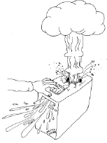
Figure 4-86.
For those who are absolutely, positively, totally paranoid: a meltdown/self-destruct system controlled by a secret key combination provides enhanced protection against data theft or intrusions by RIAA investigators asking annoying questions about file sharing.
On a more realistic level, no system is totally secure. The value of a hardware locking device is that if someone does defeat it (for instance, by figuring out how to unscrew your tamper-proof screws, or simply ripping your keypad out of the computer case with metal shears), at least you’ll know that something happened—especially if you put little dabs of paint over the screws to reveal whether they’ve been messed with. By comparison, if you use password-protection software and someone defeats it, you may never know that your system has been compromised.
Experiment 21: Race to Place
The next project is going to get us deeper into the concept of feedback, where the output is piped back to affect the input—in this case, blocking it. It’s a small project, but quite subtle, and the concepts will be useful to you in the future.
You will need:
- 74HC32 chip containing four OR gates. Quantity: 1.
- 555 timers. Quantity: 2.
- SPDT switch. Quantity: 1.
- SPST tactile switches. Quantity: 2.
- Various resistors.
- 5V supply using power regulator as before.
The Goal
On quiz shows such as
Jeopardy
, contestants race to answer each question. The first person who hits his answer button automatically locks out the other contestants, so that their buttons become inactive. How can we make a circuit that will do the same thing?
If you search online, you’ll find several hobby sites where other people have suggested circuits to work this way, but they lack some features that I think are necessary. The approach I’m going to use here is both simpler and more elaborate. It’s simpler because it has a very low chip count, but it’s more elaborate in that it incorporates “quizmaster control” to make a more realistic game.
I’ll suggest some initial ideas for a two-player version. After I develop that idea, I’ll show how it could be expanded to four or even more players.
A Conceptual Experiment
I want to show how this kind of project grows from an idea to the finished version. By going through the steps of developing a circuit, I’m hoping I may inspire you to develop ideas of your own in the future, which is much more valuable than just replicating someone else’s work. So join me in a conceptual experiment, thinking our way from a problem to a solution.
First consider the basic concept: two people have two buttons, and whoever goes first locks out the other person. I always find it helps me to visualize this kind of thing if I draw a sketch, so that’s where I’ll begin. In Figure 4-87, the signal from each button passes through a component that I’ll call a “button blocker,” activated by the other person’s button. I’m not exactly sure what the button blocker will be or how it will work, yet.
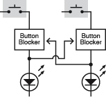
Figure 4-87.
The basic concept of the quiz project is that the output from one button should feed back to intercept the output of another button. At this point, the way in which the “button blocker” circuit works has not been figured out.
Now that I’m looking at it, I see a problem here. If I want to expand this to three players, it will get complicated, because each player must activate the “button blockers” of
two
opponents. Figure 4-88 shows this. And if I have four players, it’s going to get even more complicated.
Anytime I see this kind of complexity, I think there has to be a better way.
Also, there’s another problem. After a player lets his finger off the button, the other players’ buttons will be unblocked again. I need a latch to hold the signal from the first player’s button and continue to block the other players.
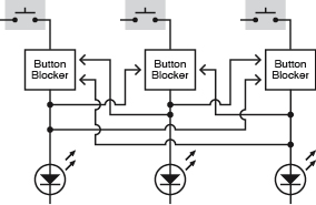
Figure 4-88.
The quiz concept becomes more complicated when an additional pushbutton is added. Now each button must block two other buttons. If a fourth button is added, the circuit will become unmanageably complex. There has to be a better way.
This now sounds even more complicated. But wait a minute, if I have a latch which allows the winning player to take his finger off his button, I don’t care if any of the buttons are being pressed anymore—including the button of the winning player. As soon as his signal is latched,
all
the buttons can be blocked. This makes things much simpler. I can summarize it as a sequence of events:
1.
First player presses his button.
2.
The signal is latched.
3.
The latched signal feeds back and blocks all the buttons.
The new sketch in Figure 4-89 shows this. Now the configuration is modular, and can be expanded to almost any number of players, just by adding more modules.
There’s something important missing, though: a reset switch, to put the system back to its starting mode after the players have had time to press their buttons and see who won. Also, I need a way to prevent players from pressing their buttons too soon, before the quizmaster has finished asking the question. Maybe I can combine this function in just one switch, which will be under the quizmaster’s control. In its Reset position, the switch can reset the system and remove power to the buttons. In its Play position, the switch stops holding the system in reset mode, and provides power to the buttons. Figure 4-90 shows this. I’ve gone back to showing just two players, to minimize the clutter of lines and boxes, but the concept is still easily expandable.

Figure 4-89.
If a latch is added below each button, it can retain one input and then block all inputs from all buttons. This simplifies the concept.
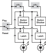
Figure 4-90.
A quizmaster switch will be needed to activate the buttons initially and then reset the circuit after a winning input has been recorded.
Now I have to deal with a logic problem in the diagram. The way I’ve drawn it, after the output from the lefthand latch goes up to the “button blockers,” it can also run down the wire to the other half of the circuit (against the direction to the arrows), because everything is joined together. In other words, if the lefthand LED lights up, the righthand LED will light up, too. How can I stop this from happening?
Well, I could put diodes in the “up” wires to block current from running down them. But I have a more elegant idea: I’ll add an OR gate, because the inputs to an OR gate are separated from each other electrically. Figure 4-91 shows this.

Figure 4-91.
To prevent the output from one latch feeding back around the circuit to the output from another latch, the outputs can be combined in an OR gate.