Make: Electronics (70 page)
Authors: Charles Platt

Experiment 29: Filtering Frequencies
In this experiment, you’ll see how self-inductance and capacitance can be used to filter audio frequencies. You’re going to build a crossover network: a simple circuit that sends low frequencies to one place and high frequencies to another.
You will need:
- Loudspeaker, 8Ω, 5 inches in diameter. Quantity: 1. Figure 5-35 shows a typical example.
- Audio amplifier, STMicroelectronics TEA2025B or similar. Quantity: 1. See Figure 5-36.
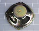
Figure 5-35.
To hear the effects of audio filters using coils and capacitors, you’ll need a loudspeaker capable of reproducing lower frequencies. This 5-inch model is the minimum required.
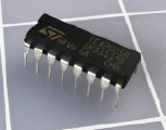
Figure 5-36.
This single chip contains a stereo amplifier capable of delivering a total of 5 watts into an 8Ω speaker when the two channels are combined.
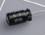
Figure 5-37.
A nonpolarized electrolytic capacitor, also known as a bipolar capacitor, looks just like an electrolytic capacitor, except that it will have “NP” or “BP” printed on it.
- Nonpolarized electrolytic capacitors (also known as bipolar). 47 μF. Quantity: 2. A sample is shown in Figure 5-37. They should have “NP” or “BP” printed on them to indicate “nonpolarized” or “bipolar.”
- Nonpolarized electrolytic capacitors (also known as bipolar). 100 μF. Quantity: 5. (Because you’ll be working with audio signals that alternate between positive and negative, you can’t use the usual polarized electrolytic capacitors. If you want to avoid the trouble and expense of ordering nonpolarized capacitors, you can substitute two regular electrolytics in series, facing in opposite directions, with their negative sides joined in the middle. Just remember that when you put capacitors in series, their total capacitance is half that of each individual component. Therefore, you would need two 220 μF electrolytics in series to create 110 μF of capacitance. See Figure 5-38.)

Figure 5-38.
You can make a nonpolarized electrolytic capacitor by putting two regular electrolytics in series. (In fact, that’s what you’d find if you opened a real nonpolarized capacitor.) The symbol at the bottom is roughly equivalent to the pair of symbols at the top; bear in mind that two capacitors in series have a total capacitance that is half that of each of them. - Potentiometer, with audio taper if possible. 100K. Quantity: 1.
- Coil, for crossover network. Quantity: 1. You can search a source such as eBay for keywords “crossover” and “coil,” but if you can’t find one at a reasonable price, you can make do with a spool of 100 feet of 20-gauge hookup wire.
- Plastic shoebox. Quantity: 1.
Procedure
The purpose of the audio amplifier chip is to provide enough power to get a decent amount of sound out of your loudspeaker. The purpose of using a 5-inch speaker is to enable you to hear lower-frequency sounds than the baby speakers that we have used previously. Bass notes have long wavelengths that small speakers are not able to generate effectively.
Maybe you remember from building the intrusion alarm that a speaker makes much more noise if you prevent the sound waves from the back of the cone from cancelling the sound waves from the front of the cone. The obvious way to achieve this is by enclosing the speaker in a box. I suggest a plastic box, because they’re cheap, and we don’t care too much about sound quality as long as we can hear at least some of the low frequencies. Figure 5-39 shows the speaker bolted into the bottom of a plastic box, and Figure 5-40 shows the box turned upside-down after snapping its lid into place.
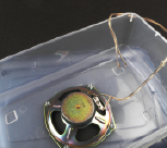
Figure 5-39.
A resonant enclosure is necessary if you want to hear some bass (lower frequencies) from your speaker. A cheap plastic shoebox is sufficient for demo purposes.
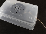
Figure 5-40.
Drill some half-inch holes in the bottom of the box, then bolt the speaker in place, running a wire out through a hole in one end. Snap on the lid, and you’re ready for not-quite-high-fidelity audio.
Normally, a speaker should be mounted in a cabinet of heavy, thick material that has a very low resonant frequency—below the limits of human hearing. To minimize the resonance of the shoebox, you can put some soft, heavy fabric inside it before you snap the lid on. A hand towel or some socks should be sufficient to absorb some of the vibration.
Adding an Amplifier
Back in the 1950s, you needed vacuum tubes, transformers, and other power-hungry heavyweight components to build an audio amplifier. Today, you can buy a chip for about $1 that will do the job, if you add a few capacitors around it, and a volume control. The TEA2025B that I’m recommending is intended for use in cheap portable cassette players and CD players, and can work in stereo or mono mode, from a power supply ranging from 3 to 9 volts. With 9 volts and the two sides of the chip bridged together to drive one 8Ω speaker, it can generate 5 watts of audio power. That doesn’t sound much compared with a typical home theater system rated at 100 watts per channel, but because loudness is a logarithmic scale, 5 watts will be quite enough to irritate any family members in the same room—and possibly even in other rooms.
If you can’t find the TEA2025B chip, you can use any alternative listed as an audio amplifier. Try to find one that is designed to drive an 8Ω speaker with up to 5 watts in mono mode. Check the manufacturer’s data sheet to see where you attach capacitors around it. Note carefully whether some of the capacitors have no polarity marked, even though they have fairly high values, such as 100 μF. These capacitors must function regardless of which way the alternating current is flowing, and I’ve marked them “NP” in my schematic in Figure 5-41, meaning “nonpolarized.” (You may find them identified as “bipolar” or “BP” in parts catalogs.) As noted in the shopping list, you can put two 220 μF capacitors in series, negative-to-negative, to get the same effect as a single 100 μF nonpolarized capacitor.
For this project, it’s essential to include the regular 100 μF electrolytic smoothing capacitor across the power supply. Otherwise, the amplifier will pick up and—yes, amplify—small voltage spikes in the circuit.
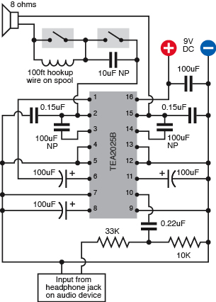
Figure 5-41.
The audio amplifier chip should be wired with capacitors around it as shown, “NP” denoting the ones that are not polarized. The acronym“BP,” meaning bipolar, is also often used to mean the same thing. The output from pins 2 and 15 of the chip can be passed through a coil or a 10 μF capacitor to demonstrate audio filtering.
The input shown in the schematic can receive a signal from a typical media player, such as a portable MP3 player, CD player, or cassette player. To connect its headphone jack to the breadboard, you can use an adapter that converts it to a pair of RCA-type audio jacks, and then stick a wire into one of them as shown in Figure 5-42. The wire will connect to the 33K resistor on the breadboard circuit. The chromed neck of the RCA jack (which is sometimes gold-plated, or at least gold-colored)
must
be connected with the negative side of your power supply on the breadboard; otherwise, you won’t hear anything. You can ignore the second output on the adapter, because we’re working in mono, here, not stereo.