Make: Electronics (72 page)
Authors: Charles Platt

Audio is a field offering all kinds of possibilities if you enjoy designing and building your own electronics.
Theory
Waveforms
If you blow across the top of a bottle, the mellow sound that you hear is caused by the air vibrating inside the bottle, and if you could see the pressure waves, they would have a distinctive profile.
If you could slow down time and draw a graph of the alternating voltage in any power outlet in your house, it would have the same profile.
If you could measure the speed of a pendulum swinging slowly to and fro in a vacuum, and draw a graph of the speed relative to time, once again it would have the same profile.
That profile is a
sine wave
, so called because you can derive it from basic trigonometry. In a right-angled triangle, the sine of an angle is found by dividing the length of the side opposite the angle by the length of the hypoteneuse (the sloping side of the triangle).
To make this simpler, imagine a ball on a string rotating around a center point, as shown in Figure 5-48. Ignore the force of gravity, the resistance of air, and other annoying variables. Just measure the vertical height of the ball and divide it by the length of the string, at regular instants of time, as the ball moves around the circular path at a constant speed. Plot the result as a graph, and there’s your sine wave, shown in Figure 5-49. Note that when the ball circles below its horizontal starting line, we consider its distance negative, so the sine wave becomes negative, too.
Why should this particular curve turn up in so many places and so many ways in nature? There are reasons for this rooted in physics, but I’ll leave you to dig into that topic if it interests you. Getting back to the subject of audio reproduction, what matters is this:
- Any sound can be broken down into a mixture of sine waves of varying frequency and amplitude.
Or, conversely:
- If you put together the right mix of audio sine waves, you can create
any sound at all
.
Suppose that there are two sounds playing simultaneously. Figure 5-50 shows one sound as a red curve, and the other as pale blue. When the two sounds travel either as pressure waves through air or as alternating electric currents through a wire, the amplitudes of the waves are added together to make the more complex curve, which is shown in black. Now try to imagine dozens or even hundreds of different frequencies being added together, and you have an idea of the complex waveform of a piece of music.
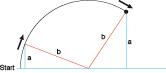
Figure 5-48.
If a weight on the end of a string (length b, in the diagram) follows a circular path at a steady speed, the distance of the weight from a horizontal center line (length a, in the diagram) can be plotted as a graph relative to time. The graph will be a sine wave, so called because in basic trigonometry, the ratio of a/b is the sine of the angle between line b and the horizontal baseline, measured at the center of rotation. Sinewaves occur naturally in the world around us, especially in audio reproduction and alternating current.

Figure 5-49.
This is what a “pure” sinewave looks like.

Figure 5-50.
When two sinewaves are generated at the same time (for instance, by two musicians, each playing a flute), the combined sound creates a compound curve. The blue sinewave is twice the frequency of the red sinewave. The compound curve (black line) is the sum of the distances of the sinewaves from the baseline of the graph.
Theory
Waveforms (continued)
You can create your own waveform as an input for your audio amplifier with the basic astable 555 timer circuit shown in Figure 5-51. You have to be careful, though, not to overload the amplifier input. Note the 680K series resistor on the output pin of the timer. Also note the 500Ω potentiometer.

Figure 5-51.
A 555 timer is wired in astable mode using the component values shown here to generate a wide range of audible frequencies when the 100K potentiometer is adjusted. After the output is reduced in power, it can feed into the amplifier chip that was used previously.
Disconnect your music player and connect the output from the 555 circuit to the input point (the 33K resistor) in the amplifier circuit shown earlier in Figure 5-41. You don’t have to worry about a separate connection on the negative side as long as the 555 timer shares the same breadboard and the negative side of its power supply.
Make sure that the 500Ω potentiometer is turned all the way to short the output from the timer to the negative side of the power supply. This functions as your volume control. Also make sure the 100K potentiometer is in the middle of its range. Switch on the power and slowly turn up the 500Ω potentiometer until you hear a tone.
Now adjust the 100K potentiometer to create a low-pitched note. You’ll find that it doesn’t have a “pure” sound. There are some buzzing overtones. This is because the 555 timer is generating square waves such as those shown in Figure 5-52, not sine waves, and a square wave is actually a sum of many different sine waves, some of which have a high frequency. Your ear hears these harmonics, even though they are not obvious when you look at a square-shaped waveform.
Route one of the connections to your loudspeaker through your spool of hookup wire, and now you should hear a much purer tone, as the buzzing high frequencies are blocked by the self-inductance of the coil. Remove the coil and substitute the 10 μF capacitor, and now you hear more buzzing and less bass.
You’ve just taken a small step toward sound synthesis. If this subject interests you, you can go online and search for oscillator circuits. For a thorough understanding of the relationship between waveforms and the sounds you hear, you’ll really need an oscilloscope, which will show you the shape of each waveform that you generate and modify.
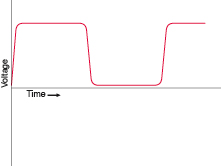
Figure 5-52.
The output from a 555 timer is either “on” or “off,” with a very fast transition between those two states. The result is an almost perfect square wave. Theoretically, this can be disassembled into a complex set of sine waves that have many different frequencies. The human ear hears the high frequencies as harsh overtones.
Experiment 30: Fuzz
Let’s try one more variation on the circuit in
Experiment 28
. This will demonstrate another fundamental audio attribute: distortion.
You will need:
- One more 100K potentiometer.
- Generic NPN transistors: 2N2222 or similar. Quantity: 2.
- Various resistors and capacitors.
Background
Clipping
In the early days of “hi-fi” sound, engineers labored mightily to perfect the process of sound reproduction. They wanted the waveform at the output end of the amplifier to look identical with the waveform at the input end, the only difference being that it should be bigger, so that it would be powerful enough to drive loudspeakers. Even a very slight distortion of the waveform was unacceptable.
Little did they realize that their beautifully designed tube amplifiers would be abused by a new generation of rock guitarists whose intention was to create as much distortion as possible.
The most common form of waveform abuse is technically known as “clipping.” If you push a vacuum tube or a transistor to amplify a sine wave beyond the component’s capabilities, it “clips” the top and bottom of the curve. This makes it look more like a square wave, and as I explained in the section on waveforms, a square wave has a harsh, buzzing quality. For rock guitarists trying to add an edge to their music, the harshness is actually a desirable feature.
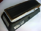
Figure 5-53.
This Vox Wow-Fuzz pedal was one of the early stomp boxes, which deliberately induced the kind of distortion that audio engineers had been trying to get rid of for decades.
The first gadget to offer this on a commercial basis was known as a “fuzz box,” which deliberately clipped the input signal. An early fuzz box is shown in Figure 5-53. The clipping of a sine wave is shown in Figure 5-54.

Figure 5-54.
When a sinewave (top) is passed through an amplifier which is turned up beyond the limit of its components (shown as dashed lines, center), the amplifier chops the wave (bottom) in a process known as “clipping.” The result is close to a square wave and is the basic principle of a fuzz box commonly used to create a harsh guitar sound.