125 Physics Projects for the Evil Genius (48 page)
Read 125 Physics Projects for the Evil Genius Online
Authors: Jerry Silver

– solar cell
– insulated wire (you need two 15-inch lengths with the insulation removed)
– wire stripper (a pen knife or a pair of scissors will do)
– ammeter (if you have a multimeter, configure it as an ammeter)
– soldering iron with (resin core Pb/Sn) solder
– a third hand (or a second person to help solder)
- or a commercially available light meter, such as shown in
Figure 81-1
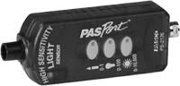
Figure 81-1
Light sensor. Courtesy PASCO
.
- light bulb (
not a focused
source, such as a laser or flashlight) - tape measure
- dark room
- Plug in the soldering iron. Make sure the tip is in a safe place. It gets very hot in a few minutes and should not be in contact with anybody or anything that is flammable.
- Place the solar cell with the blue side up and locate a pad near the edge intended for wire attachment.
- As the soldering iron gets hot, “wet” the tip by melting some of the solder on the soldering iron tip.
- Strip about ¼ inch of the insulation from the end of each of two 15-inch lengths of wire.
- Position the wire on one of the contact pads on the edge of the solar cell.
- Position the end of solder from the coil on the pad and near the wire.
- Touch the soldering iron to the wire to get it as hot as possible. This may happen a bit faster if it is at first raised above the solar cell to avoid heat being conducted by the solar cell. You also want to avoid overheating the solar cell, which could cause it to short out if the heat is excessive. And, you should avoid having any electrical contact—whether it is the wire touching or solder—between the
front pad and the back of the solar cell. This can short out the solar cell and prevent it from generating an electrical output. - Touch the solder to the heated wire and, as it melts, have some of the molten solder form a bridge to the solder pad.
- Remove the soldering iron and don’t move until the solder solidifies. If done properly, the solder should stick to both the solar cell pad and the wire forming a mechanical bond.
- Similarly attach a wire anywhere to the back of the solar cell.
- Attach the wire coming from the back of the solar cell to the positive terminal of the ammeter. Attach the wire coming from the front of the solar cell to the negative terminal of the ammeter.
- At this point, you can (carefully) hold the solar cell or mount it by gluing or taping it to a board. Remember, solar cells are extremely fragile and will break if the slightest pressure is put on them. The solar cell may still function if fractured, but reasonable caution can avoid that.
1. Position the light bulb, so a few meters are in front of it without obstruction.
2. Turn off the room lights.
3. Pick a location such as about 25 cm from the light bulb and take a reading on the light meter. (This starting distance is arbitrary and depends on the sensitivity of the meter you are using.)
4. Record the distance (any choice of unit, inches, or meters can work, but be consistent throughout your investigation). Record the light intensity, as shown in
Figure 81-2
, in the units in which the light meter is calibrated (such as lumem/m
2
lm/m
2
).
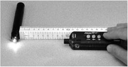
Figure 81-2
Courtesy PASCO
.
Expected Results5. If you are using the solar cell, orient it so it is perpendicular to the line between you and the source of light; the unit of measurement will be in amps. Be careful not to block the front of the solar cell with your fingers, which can compromise the accuracy of your reading.
The farther away you get, the less intense the light becomes.
The rate of drop-off is not linear. The farther away you get, the faster the light intensity falls off.
More specifically, the light intensity drops off as the inverse-square of the distance. This is shown graphically in
Figure 81-3
.
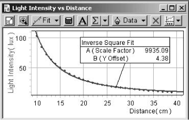
Figure 81-3
Courtesy PASCO
.
Light intensity is related to the distance from its source according to the equation:
I = I
o
/r
2
where
I
represents light intensity at distance,
r
, between the light source and the point of measurement for an initial intensity, I
o
.
A similar inverse square law relationship can be found with a source of sound and a sound intensity meter.
Light intensity drops off as the inverse square of the distance from the source of light.
How do we know that light is a wave? Thomas Young’s double slit experiment with a diffraction grating
.
Sir Isaac Newton was definitely no slouch when it came to physics. And, if you asked Newton whether light was a wave or a particle, he would say it was a particle. Newton was actually correct for reasons that would not become clear until several centuries later. Thomas Young proved the opposite was true—that light was (also) a wave. Today, we recognize that light has
both
particle and wave-like behavior. We re-create Young’s experiment in this project to explore light’s wave-like behavior. Young observed the effect of light emerging from two small slits in an opaque plate. Instead of two slits, you create a similar effect using a diffraction grating which lets you explore the effect of dozens of openings.
- diffraction grating available from scientific supply companies, including
– Edmunds 3001307 13,500 lines/inch
http://scientificsonline.com
– PASCO OS 9127 600 lines/mm (15,000 lines/inch)
http://store.pasco.com
– Frey Scientific 1559099721 15,000 lines/inch
http://www.freyscientific.com
- laser pointer
- meterstick
- ruler with metric divisions (centimeters)
- index card
- dark room
- holders to support rulers
- holders for card, diffraction grating, and grating
- Mount the diffraction grating with the lines oriented up and down.
- Mount the index card, so it is parallel to the diffraction grating.
- Arrange the meterstick, so you can monitor the distance between the diffraction grating and the screen as you adjust this distance. (If it is convenient to set up, one possible approach is to attach the diffraction grating and screen directly to the meterstick, and then determine the distance between them from the difference in the readings.) A good starting distance is several centimeters.
- Hold (or secure) the laser pointer, so the laser beam is directed perpendicular to the diffraction grating. See
Figure 82-1
. - Darken the room and turn on the laser. (Caution: As with any project involving a laser, use a low-power laser, such as a laser pointer, and be careful to avoid contact with anyone’s eyes.)
- You should see the path of the laser through the diffraction grating. The brightest spot is called the
central maximum
. Draw a vertical line through the central maximum. - On either side of the central maximum, you should also find a much dimmer spot. This is called the
first order line
. (It is more like a spot than a line in our case because we are using light from a laser, rather than the vertical slits originally used by Young.)

Figure 82-1
Apparatus used for this project
.
A pattern of spots is produced to the right and left of the center line. These are the result of the constructive interference of waves. This proves that light is a wave. Or, more accurately, in addition to having particle-like properties, light is also a wave.
If the distance to the screen is increased, the distance between the bright spots also increases. The distance between the laser and the diffraction grating should not matter, however, because the light strikes the diffraction grating in a perpendicular direction, regardless of how far it is coming from.
When waves meet, if the crests occur at the same time, the waves add. This is called
constructive interference
. If when waves meet a crest and trough come together, the waves cancel. This is called
destructive interference
.
Interference is a basic characteristic of waves. The light- and dark-spot pattern is the result of interference of the waves emerging from two adjacent openings in the diffraction grating.
Once you locate the first order bright spots, you can try to locate the second, third, and possibly higher order lines. This may require a very dark room.
This project recreates one of the most significant experiments of the twentieth century in which Thomas Young demonstrated that light is a wave. Interference patterns are a unique characteristic of waves. Because light in this experiment exhibits an interference pattern, it proves conclusively that light is a wave.