Breast Imaging: A Core Review (9 page)
Read Breast Imaging: A Core Review Online
Authors: Biren A. Shah,Sabala Mandava
Tags: #Medical, #Radiology; Radiotherapy & Nuclear Medicine, #Radiology & Nuclear Medicine

Answer choice A is incorrect because chemical shift artifact is an artifact that results from the different resonances of the hydrogen in fat and water. It is most commonly seen in non–fat-suppressed sequences (e.g., non– fat- suppressed T1-weighted) and results in signal void or bright signal at a fat–water interface. Answer choice B is incorrect because wrap or aliasing artifact occurs when tissue extends beyond the field of view (FOV), causing signal from tissues outside the FOV to be superimposed on structures within the FOV. It occurs in the phase-encoding direction. This artifact is commonly seen with patients’ arms in breast MRI practice. Susceptibility artifact is usually due to metallic artifact(s) that appear as signal voids on gradient-echo sequences. On spin-echo sequences, a signal flare component may be seen in addition to the signal void. Answer choice D is incorrect. There is no significant motion on this image. Motion artifact is one of the most commonly encountered artifacts affecting breast MRI. Motion can arise from patient motion or cardiac, respiratory, or great vessel motion. All motions propagate in the phase-encoding direction despite the direction of the motion. Phase-encoding direction should be left to right for axial sequences and superior to inferior for sagittal sequences to reduce the effect of cardiac and respiratory motion on the breasts.
42b
Answer C.
Shimming the magnet (optimizing field homogeneity) of an MR imaging unit can sometimes correct inhomogeneous fat saturation artifact.
Answer choice A is incorrect because enlarging the field of view can correct wrap or aliasing artifact. Answer choice B is incorrect because reducing patient motion can prevent phase-encoding or ghosting artifact. Answer choice D is incorrect because increasing bandwidth per pixel of the imaging sequence can reduce chemical shift artifact. Answer choice E is incorrect because checking the radiofrequency (RF) shield for a leak might be the cause for RF interference.
References: Harvey JA, Hendrick E, Coll JM, et al. Breast MR imaging artifacts: How to recognize and fix them.
Radiographics
2007;27:S131–S145.
Ojeda-Fournier H, Choe KA, Mahoney MC. Recognizing and interpreting artifacts and pitfalls in MR imaging of the breast.
Radiographics
2007;27:S147–S164.
43
Answer D.
The patient was coughing during the exam, and therefore the ghosting artifact seen on the image is due to patient motion. Artifact from patient motion propagates in the phase-encoding direction, regardless of the direction of the motion. Motion can result in blurring of moving tissues but can also cause a structured noise pattern, resulting in “ghosting” of brighter moving tissues in the phase-encoding direction.
Answer choice A is incorrect because chemical shift artifact is an artifact that results from the different resonances of the hydrogen in fat and water. It is most commonly seen in non–fat-suppressed sequences (e.g., non– fat- suppressed T1-weighted) and results in signal void or bright signal at a fat–water interface. Answer choice B is incorrect because wrap or aliasing artifact occurs when tissue extends beyond the field of view (FOV), causing signal from tissues outside the FOV to be superimposed on structures within the FOV. It occurs in the phase-encoding direction. This artifact is commonly seen with patients’ arms in breast MRI practice. Answer choice C is incorrect. Susceptibility artifact is usually due to metallic artifact(s) that appear as signal voids on gradient-echo sequences. On spin-echo sequences, a signal flare component may be seen in addition to the signal void. Answer choice E is incorrect. The fat saturation is homogeneous on this T2 STIR image.
References: Harvey JA, Hendrick E, Coll JM, et al. Breast MR imaging artifacts: How to recognize and fix them.
Radiographics
2007;27:S131–S145.
Ojeda-Fournier H, Choe KA, Mahoney MC. Recognizing and interpreting artifacts and pitfalls in MR imaging of the breast.
Radiographics
2007;27:S147–S164.
44
Answer C.
There is a local signal intensity void with a partially surrounding area of high signal intensity and image distortion in the sternum. This represents metallic susceptibility artifact from sternotomy wires.
References: Harvey JA, Hendrick E, Coll JM, et al. Breast MR imaging artifacts: How to recognize and fix them.
Radiographics
2007;27:S131–S145.
Ojeda-Fournier H, Choe KA, Mahoney MC. Recognizing and interpreting artifacts and pitfalls in MR imaging of the breast.
Radiographics
2007;27:S147–S164.
45
Answer D.
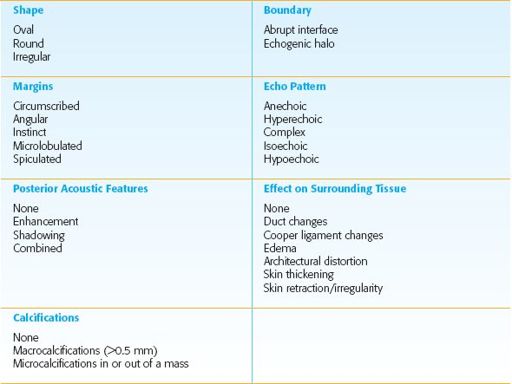
The lesion shown is an irregular hypoechoic mass with angular margins. This mass is suspicious (BI-RADS 4), and tissue sampling was recommended. The mass was invasive ductal carcinoma.
American College of Radiology BI-RADS Ultrasound Lexicon Descriptors
References: American College of Radiology (ACR).
The ACR Breast Imaging Reporting and Data System (BI-RADS). BI-RADS-Ultrasound
. Reston, VA: American College of Radiology; 2003:9–52.
Ikeda D.
Breast Imaging: The Requisites
. 2nd ed. St. Louis, MO: Elsevier Mosby; 2011:97–100.
46
Answer D.
The calcifications shown are lucent centered and are often pathognomonic for dermal calcifications. Dermal calcifications are most commonly seen along the inframammary fold parasternally, axilla, and areola. Unusual forms can be confirmed as skin calcifications by performing a dermal calcification study. Dermal calcifications will be in the skin directly under the skin marker on the tangential mammogram view.
References: American College of Radiology (ACR).
The ACR Breast Imaging Reporting and Data System (BI-RADS). BI-RADS-Mammography
. Reston, VA: American College of Radiology; 2003:61–107.
Ikeda D.
Breast Imaging: The Requisites
. 2nd ed. St. Louis, MO: Elsevier Mosby; 2011:76–79.
47
Answer B.
On a mediolateral oblique (MLO) projection view the pectoralis muscle should be concave and extend inferior to the posterior nipple line (PNL). The PNL describes an imaginary line drawn from the nipple to the pectoralis muscle or film edge and perpendicular to the pectoralis muscle. The length of the PNL on the CC view should be 1 cm or less of its length on the MLO view. The pectoralis muscle should be seen whenever possible on the craniocaudal view and therefore there is no required thickness. When the pectoralis muscle is seen, one can be confident that the posterior tissue has been adequately included on the image. The CC view is not exaggerated to include the axillary tail. This view is that of an exaggerated craniocaudal lateral view (XCCL).
Reference: Ikeda D.
Breast Imaging: The Requisites
. 2nd ed. St. Louis, MO: Elsevier Mosby; 2011: 6, 51.
48
Answer A.
There is blurring of the image due to patient motion during the mammogram exam.
Answer choice B is incorrect because ghost image is when the image receptor retains a ghost image of a previous image and becomes visible on the next image taken. This finding is caused by low detector temperature. Allowing the detector to warm up properly usually clears the problem. With improvement of detector technology and systems that better regular detector temperature, this problem is less common.
Answer choice C is incorrect because gridlines are subtle cross-hatch pattern lines on an image. Gridlines are caused by the grid speed parameter set incorrectly. Grid speed parameter is set by a service engineer and cannot be changed by the technologist.
Answer choice D is incorrect because no radiopaque particles are seen in the axillary region.
References: Geiser WR, Haygood TM, Santiago L, et al. Challenges in mammography: Part 1, artifacts in digital mammography.
AJR Am J Roentgenol
2011;197(6):W1023–W1030.
Shah BA, Fundaro GM, Mandava S.
Breast Imaging Review: A Quick Guide to Essential Diagnoses
. 1st ed. New York, NY: Springer; 2010:2–5.
49
Answer C.

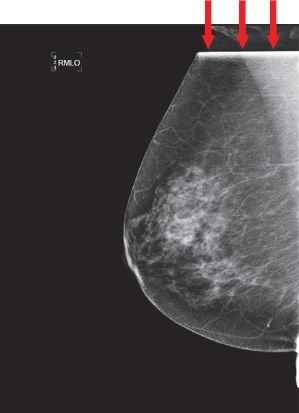
This case demonstrates a readout failure artifact. There is a line artifact that was caused by software processing failure (see
red arrows
). This error can correct itself, or a new detector readout sequence file can be installed.
Reference: Geiser WR, Haygood TM, Santiago L, et al. Challenges in mammography: Part 1, artifacts in digital mammography.
AJR Am J Roentgenol
2011;197(6):W1023–W1030.
50
Answer B.
Gridlines resemble grid artifacts in screen film. There is miscalibration in the gain calibration file resulting in gridlines on all subsequent images.
Reference: Geiser WR, Haygood TM, Santiago L, et al. Challenges in mammography: Part 1, artifacts in digital mammography.
AJR Am J Roentgenol
2011;197(6):W1023–W1030.
51
Answer: A
. Breast MRI that is performed to evaluate a patient for breast cancer requires the use of a contrast agent. Gadolinium contrast is generally not necessary in the evaluation of implant integrity and rupture. Breast MRI is most commonly performed using one of the gadolinium-based low-molecular-weight MRI contrast agents. Gadolinium contrast should be given as a bolus with a standard dose of 0.1 mmol/kg followed by a saline flush of at least 10 mL.
Reference: American College of Radiology
ACR Practice Guideline for the Performance of Contrast-Enhanced Magnetic Resonance Imaging (MRI) of the Breast
. 2013.
www.acr.org/~/media/ ACR/Documents/PGTS/guidelines/MRI_Breast.pdf
52
Answer B.
The perpendicular distance from the nipple to the pectoralis muscle on the MLO is used as a reference for adequacy of the CC view. The measurement on the CC view (taken as the distance from the nipple to the pectoralis or the back of the image) should be within 1.0 cm of the MLO measurement.
Reference: Ikeda D.
Breast Imaging: The Requisites
. 2nd ed. St. Louis, MO: Elsevier Mosby; 2011:5–7.
53a
Answer B.
Phase wrap, also known as aliasing artifact or wraparound artifact, occurs when not all of the signal-producing tissue is within the field of view (FOV). This artifact occurs in the phase-encoding direction. The signal from the excited tissue outside the FOV becomes superimposed on structures within the FOV through misregistration during Fourier transform reconstruction.
Fat saturation is important for breast cancer detection on MRI. High signal of fat interferes with the detection of enhancing lesions. MR imaging unit software automatically identifies the water peak as the highest signal peak, and fat is suppressed by applying saturation pulses at a frequency of 3.5 ppm (224 Hz at 1.5 T) below the water peak. To effectively suppress the protons in the fat molecules, the correct range of frequencies must be selected. Sometimes in the presence of an unexpected variation in the magnetic field, there will be protons in fat that are precessing out of the range of frequencies included in the suppression pulse. These protons will not be suppressed, and the fat containing these protons will maintain its brighter signal. This phenomenon results in inhomogeneous suppression of the fat signal within the breast. Inhomogeneous fat saturation is a common problem and cannot be corrected for. However, shimming the magnet (optimizing field homogeneity) of an MR imaging unit can correct some of the artifact.
Other books
My Calling by Lyssa Layne
Priestess of the Nile by Veronica Scott
Rayuela by Julio Cortazar
Demons by Bill Nagelkerke
The Recruitment: Rise of the Free Fleet by Michael Chatfield
The Memory of Running by McLarty, Ron
Play Softly (The Devil's Share Book 4) by L.P. Maxa
The Tycoon's Revenge (Baby for the Billionaire - Book One) by Anne, Melody
French Passion by Briskin, Jacqueline;
Counting Stars by David Almond
