But How Do It Know? - the Basic Principles of Computers for Everyone (16 page)
Read But How Do It Know? - the Basic Principles of Computers for Everyone Online
Authors: J Clark Scott

The simplified diagram shows this to be the one special bit in the computer that has an output but does not have any inputs.

This bit has a name. It is called the clock. Now we usually think of a clock as a thing with a dial and hands, or some numbers on a screen, and we have seen such clocks in the corner of a computer screen. Unfortunately, someone named this type of bit, a clock, and the name stuck with the computer pioneers. It could have been called the drumbeat or the pacesetter or the heart or the rhythm section, but they called it a clock. That is what we will mean when we say clock throughout the rest of this book. I guess it’s a clock that ticks, but doesn’t have a dial. If we want to talk about the type of clock that tells you what time it is, we will call it a ‘time of day clock,’ or ‘TOD clock’ for short. But the word ‘clock’ will mean this type of bit.
How quickly does this clock go on and off? These days it is well over a billion times per second, or several gigahertz. This is one of the main characteristics that computer companies tell you about to show you how great their computers are. When you see computers for sale, the speed that they advertise is the speed of its clock. The faster a computer is, the more expensive it is, because it can do more things in one second. It is the speed of this single bit going on and off that sets the tempo for the whole computer.
To move data via the bus, we need first to enable the output of one and only one register, so that its electricity can travel through the bus to the inputs of other registers. Then, while the data is on the bus, we want to turn the set bit of the destination register on and off. Since the destination register captures the state of the bus at the instant that the set bit goes off, we want to make sure that it goes off before we turn off the enable bit at the first register to make sure that there are no problems.
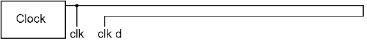
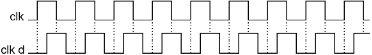
Let us first attach a length of wire to the output of the clock. This will delay the electricity slightly. We want it delayed about one quarter of a cycle.
If we show the original clock output (clk) and the delayed clock output (clk d) on a graph, they will look like this:
Now we’re going to do something fairly simple. We will take the original clock and the delayed clock, and both AND them and OR them to create two new bits, like so:
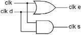
One of the new bits is on when either ‘clk’ or ‘clk d’ are on, and the other new bit is on only when both ‘clk’ and ‘clk d’ are on. The graph of the inputs and outputs of the AND and OR gates is shown here. They are both still going on and off regularly, but one of them is on for longer than it is off, and the other one is off for longer than it is on. The on time of the second is right in the middle of the on time of the first.

Notice that they have names, ‘clk e,’ which stands for clock enable, and ‘clk s,’ which stands for clock set. And what do you know, these two bits have the perfect timing to move a byte of data from one register, across the bus, and into another register. Just connect ‘clk e’ to the enable bit of the ‘from’ register, and connect ‘clk s’ to the set bit of the ‘to’ register.
Here is a single on/off cycle of these two bits.

If you look at the timing here, this meets our requirements of needing to first enable the output of a register, and then, after the data has a little time to travel down the bus, to turn the set bit of the destination register on and off before turning the enable bit off at the first register.
Of course, these clock bits cannot just be connected directly to every register. There must be other gates in between, that only allow one register to get an enable at any one time, and only the desired register(s) to receive a set. But all enables and sets ultimately come from these two bits because they have the right timing.
Since we will use clk, clk e and clk s throughout the computer, this is the diagram we will use to show the clock:

Doing Something Useful
Let’s say that we want to do something useful, like adding one number to another number. We have a number in R0, and there is another number in R1 that we want to add to the number in R0. The processor we have built so far has all of the connections to do this addition, but it will take more than one clock cycle to do it.
In the first clock cycle, we can enable R1 onto the bus, and set it into TMP.
In the second cycle we can enable R0 onto the bus, set the ALU to ADD, and set the answer into ACC.
In the third cycle, we can enable ACC onto the bus, and set it into R0.
We now have the old value of R0, plus R1 in R0. Perhaps this doesn’t seem very useful, but it is one of the kind of small steps that computers do. Many such small steps make the computer seem to be able to do very complex things.
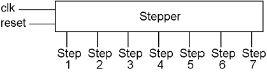
Thus we see that for the processor to do something useful, it takes several steps. It needs to be able to do actions in a sequence. We need another piece inside this ‘Control Section.’
Step by Step
This chapter introduces a new part called the “Stepper.” First, we will describe the completed stepper, showing exactly what it does. After that, we will see exactly how it is built. If you happen to trust your author enough to believe that such a stepper can be built out of gates, and you’re in such a hurry that you want to skip the ‘how it is built’ part of the chapter, you might still understand the computer.
Here is a complete stepper.