But How Do It Know? - the Basic Principles of Computers for Everyone (15 page)
Read But How Do It Know? - the Basic Principles of Computers for Everyone Online
Authors: J Clark Scott


All seven devices are connected to input ‘a,’ the devices that have two inputs are also connected to input ‘b.’ All seven devices are connected to the inputs at all times, but each output is attached to one of those enablers. The wires that turn the enablers on, are connected to the outputs of a decoder, thus only one enabler can be on at a given time. Seven of the decoder’s outputs enable a single device to continue on to the common output, ‘c.’ The eighth output of the decoder is used when you don’t want to select any device at all. The three input wires to the decoder are labeled ‘op,’ because they choose the desired ‘operation.’
The one little complication here is the carry bits from the adder, and the ‘shift in’ and ‘shift out’ bits from the shifters. These are used in very similar ways, and so from here on out we will refer to all of them as carry bits. The adder and both shifters take carry as an input, and generate carry as an output. So the three carry inputs are connected to a single ALU input, and one of the three outputs is selected along with the bus output of its device. Look at the rightmost output of the 3X8 decoder above, and see that it enables both the adder bus and the adder carry bit.
What do we have here? It is a box that has two bus inputs, one bus output and four other bits in and four other bits out. Three of the input bits select which “operation” will take place between the input and output buses. Again, now that we know what’s in it and how it works, we don’t need to show all of its parts. Here is a simplified way to draw it:
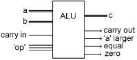
Notice that the three single bit inputs labeled “op,” above, can have eight different combinations. Seven of those combinations select one of the devices described previously. The eighth combination does not select any output byte, but the ‘a larger’ and ‘equal’ bits still work, as they do at all times, so this is the code to choose if you only want to do a comparison.
The combination of bits at ‘op’ mean something. That sounds like another code. Yes, here is a three-bit code that we will make use of soon.
000 | ADD | Add |
001 | SHR | Shift Right |
010 | SHL | Shift Left |
011 | NOT | Not |
100 | AND | And |
101 | OR | Or |
110 | XOR | Exclusive OR |
111 | CMP | Compare |
The Arithmetic and Logic Unit is the very center, the heart of the computer. This is where all of the action happens. I’ll bet this is a lot less complicated than you thought.
More of the Processor
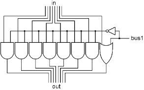
There is one more little device we need. It is a very simple thing, it has a bus input, a bus output and one other input bit. It is very similar to an enabler. Seven of the bits go through AND gates, and one of them goes through an OR gate. The single bit input determines what happens when a byte tries to pass through this device. When the ‘bus 1’ bit is off, all of the bits of the input bus pass through to the output bus unchanged. When the ‘bus 1’ bit is on, the input byte is ignored and the output byte will be 0000 0001, which is the number 1 in binary. We will call this device a ‘bus 1’ because it will place the number 1 on a bus when we need it.
Now we can put this ‘bus 1’ and the ALU into the CPU. We will change where the wires go in and out of the ALU so it fits our diagram better. The bus inputs come in the top, the bus output comes out the bottom and all of the input and output bits are on the right.
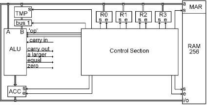
The output of the ALU is connected to ACC. ACC receives, and temporarily stores, the result of the most recent ALU operation. The output of ACC is then connected to the bus, so its contents can be sent somewhere else as needed.
When we want to do a one input ALU operation, we have to set the three ‘op’ bits of the ALU to the desired operation, enable the register we want onto the bus, and set the answer into ACC.
For a two input ALU operation, there are two steps. First we enable one of the registers onto the bus and set it into TMP. Then we enable the second register onto the bus, choose the ALU operation, and set the answer into ACC.
As you can see, we can now move bytes of data to and from RAM, to and from the Registers, through the ALU to ACC, and from there, into a register or RAM if we turn the appropriate enable and set bits on and off at the right time. This is what happens inside of computers. That’s not so complicated, is it?
There is only one thing missing here, and that has to do with all of these control bits on the registers, ALU and RAM. The RAM has three control bits, one to set MAR, one to set the currently selected byte in, one to enable the currently selected byte out. Each of the registers, R0, R1, R2, R3 and ACC have a set and an enable bit, TMP only has a set bit, bus 1 has a control bit, and the ALU has those three ‘op’ bits that select the desired operation.
We need something that will turn all of these control bits on and off at the appropriate times so we can do something that is useful. Now it is time to look into that box labeled ‘Control Section.’
The Clock
We need to turn the appropriate control bits on and off at the appropriate times. We will look at the appropriate bits later, first we will look at the appropriate times.
Here is a new kind of drawing, we will call it a graph. It shows how one bit changes over time. Time starts on the left and marches forward to the right. The line on the graph has two possible positions, up means the bit is on, and down means the bit is off.
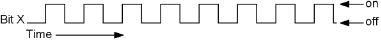
This graph shows bit ‘X’ going on and off, on and off regularly. There could be a time scale on the bottom to show how fast this is happening. If the whole width of the page represented one second, then bit ‘X’ would be going on and off about eight times per second. But we won’t need a time scale in these graphs, as we will only be concerned with the relative timing between two or more bits. The speed in an actual computer will be very fast, such as the bit going on and off a billion times per second.
When something repeats some action regularly, one of those actions, individually, is called a cycle. The graph above shows about eight cycles. You can say that from one time the bit turns on to the next time the bit turns on is a cycle, or you can say that from the middle of the off time to the middle of the next off time is the cycle, as long as the cycle starts at one point in time when the bit is at some stage of its activity, and continues until the bit gets back to the same stage of the activity again. The word ‘Cycle’ comes from the word ‘circle,’ so when the bit comes full circle, that is one cycle.
There was a scientist who lived in Germany in the 1800’s who did some of the early research that led up to radio. His name was Heinrich Hertz, and among other things, he studied electricity that was going on and off very quickly. Some decades after his death, it was decided to use his name to describe how fast electricity was going on and off, or how many cycles occurred per second. Thus, one Hertz (or Hz for short) means that the electricity is going on and off once per second. 500 Hz means 500 times per second. For faster speeds we run into those ancient languages again, and one thousand times per second is called a kilohertz or kHz for short. Going on and off a million times per second is called a megahertz, or mHz for short, and a billion times is called a gigahertz, or gHz for short.
Every computer has one special bit. All other bits in a computer come from somewhere, they are set on and off by other bits or switches. This one special bit turns on and off all by itself. But there is nothing mysterious about it, it just goes on and off very regularly and very quickly. This special bit is built very simply, like this:

This seems a silly thing to do. Just connect a NOT gate’s output back to its input? What will this do? Well, if you start with the output on, the electricity travels back to the input, where it enters the gate which turns the output off, which travels back to the input which turns the output on. Yes, this gate will just go on and off as quickly as possible. This will actually be too fast to be used for anything, and so it can be slowed down just by lengthening the wire that makes the loop.