Make: Electronics (25 page)
Authors: Charles Platt

Theory
See the current (continued)
In my little experiment, I found that the maximum current at A2 was 33mA. A simple calculation using Ohm’s Law showed me that this meant the transistor’s internal resistance was near zero. This is why you should protect a transistor with some additional resistance in the circuit. If you don’t, its low internal resistance would allow a huge current flow that would immediately burn it out.
What about the other end of its range? When it passes only 1.9 mA, the transistor has an internal resistance of around 6,000Ω. The conclusion is that depending how much current you apply to this transistor, its internal resistance varies between zero and 6,000Ω, approximately.
So much for the theory. Now what can we do with a transistor that’s fun, or useful, or both? We can do
Experiment 11
!

Figure 2-95.
This is basically the same as the previous circuit, with a potentiometer added and the LED removed. Component values:
R1: 180Ω
R2: 10K
R3: 180Ω
R4: 10K
P1: 1M linear potentiometer
Q1: 2N2222 transistor

Figure 2-96.
The meter is measuring current flowing from the potentiometer into the base of the transistor at position A1 (see Figure 2-95).
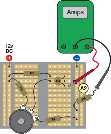
Figure 2-97.
One end of resistor R3 has been unplugged from the breadboard so that the meter now measures current flowing out through the emitter of the transistor, into R3, at position A2.
Experiment 11: A Modular Project
You will need:
- AC adapter, breadboard, wire, and meter.
- LED. Quantity: 1.
- Resistors, various.
- Capacitors, various.
- Transistor, 2N2222 or similar. Quantity: 2.
- 2N6027 programmable unijunction transistor (PUT). Quantity: 2.
- Miniature 8Ω loudspeaker. Quantity: 1.
So far, I’ve described small circuits that perform very simple functions. Now it’s time to show how modules can be combined to create a device that does a bit more.
The end product of this experiment will be a circuit that makes a noise like a small siren, which could be used in an intrusion alarm. You may or may not be interested in owning an alarm, but the four-step process of developing it is important, because it shows how individual clusters of components can be persuaded to communicate with each other.
I’ll begin by showing how to use a transistor to make a solid-state version of the oscillating circuit that you built with a relay in
Experiment 8
. The relay, you may remember, was wired in such a way that the coil received power through the contacts of the relay. As soon as the coil was energized, it opened the contacts, thus cutting off its own power. As soon as the contacts relaxed they restored the power, and the process repeated itself.
There’s no way to do this with a single bipolar transistor. You actually need two of them, switching each other on and off, and the way that this works is quite hard to understand. An easier option is to use a different thing known as a programmable unijunction transistor, or PUT.
Unijunction transistors were developed during the 1950s, but fell into disuse when simple silicon chips acquired the ability to perform the same kinds of functions, more accurately and more cheaply. However, the so-called programmable unijunction transistor is still widely available, often used in applications such as lamp dimmers and motor controllers. Because its primary use is in generating a stream of pulses, it’s ideal for our purposes.
If you put together the components shown in Figure 2-98, the LED should start flashing as soon as you apply power.
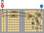
Figure 2-98.
Assemble these components, apply power, and the LED should start flashing.
R1: 470K
R2: 15K
R3: 27K
C1: 2.2 μF electrolytic capacitor
D1: LED
Q1: 2N6027 programmable unijunction transistor
Note that this circuit will work on 6 volts. You won’t damage anything if you run it with 12 volts, but as we continue adding pieces to it, you’ll find that it actually performs better at 6 volts than at 12. If you read the next section, “Essentials: All about programmable unijunction transistors,” you’ll find out how the circuit works.
Essentials
All about programmable unijunction transistors
The schematic symbol for a programmable unijunction transistor, or PUT, looks very different from the symbol for a bipolar transistor, and its parts are named differently, too. Nevertheless, it does have a similar function as a solid-state switch. The symbol and the names of the three connections are shown in Figure 2-99.
Note that this is a rare case (maybe the only one in the whole of electronics!) in which you won’t run into confusing variations of the basic schematic symbol. A PUT always seems to look the way I’ve drawn it here. Personally I think it would be clearer if we added a circle around it, but no one seems to do that, so I won’t, either.
The 2N6027 is probably the most common PUT, and seems to be standardized in its packaging and pin-outs. I’ve only seen it in a plastic module rather than a little tin can. Figure 2-100 shows the functions of the leads if your 2N6027 is manufactured by Motorola or On Semiconductor. If you have one from another source, you should check the data sheet.
Note that the flat side of the plastic module faces the opposite way around compared with the 2N2222 bipolar transistor, when the two devices are functioning similarly.
The PUT blocks current until its internal resistance drops to allow flow from the “anode” to the “cathode.” In this way, it seems very similar to an NPN transistor, but there’s a big difference in the circumstances that cause the PUT to lower its resistance. The voltage at the anode determines when the PUT allows current to flow.
Suppose you start with, say, 1 volt at the anode. Slowly, you increase this voltage. The transistor blocks it until the anode gets close to 6 volts. Suddenly this pressure breaks down the resistance and current surges from the anode to the cathode. If the voltage goes back down again, the transistor reverts to its original state and blocks the flow.
I’ve included another version of the “finger on the button” drawing to convey this concept. The voltage on the anode is itself responsible for pushing the button that opens the pathway to the cathode. See Figure 2-101.

Figure 2-99.
The schematic symbol for a PUT.
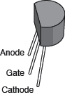
Figure 2-100.
In PUTs manufactured by On Semiconductor and Motorola, the leads have these functions.
Essentials
All about programmable unijunction transistors (continued)
This may cause you to wonder what the function of the gate is. You can think of it as “assisting” the finger on the button. In fact, the gate is the “programmable” part of a PUT. By choosing a voltage for the gate, you establish the threshold point when current starts to flow.
Here’s a simple take-home summary:
- The anode has to be more positive than the cathode, and the gate should be between those two extremes.
- If anode voltage increases above a threshold point, current bursts through and flows from the anode to the cathode.
- If anode voltage drops back down below the threshold, the transistor stops the flow.
- The voltage you apply to the gate determines how high the threshold is.
- The gate voltage is adjusted with two resistors, shown as R1 and R2 in the simple schematic in Figure 2-102. Typically, each resistor is around 20K. The PUT is protected from full positive voltage by R3, which can have a high value, 100K or greater, because very little current is needed to bias the transistor.
- You add your input signal in the form of positive voltage at the anode. When it exceeds the threshold, it flows out of the cathode and can work some kind of output device.
The only remaining question is how we make a PUT oscillate, to create a stream of on/off pulses. The answer is the capacitor that you included in the circuit that you breadboarded at the beginning of
Experiment 11
.
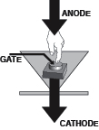
Figure 2-101.
When voltage at the anode of a PUT crosses a threshold (determined by a preset voltage at the gate), current breaks through and surges from the anode to the cathode. In this sense, the anode voltage acts as if it presses a button itself to open a connection inside the PUT, with some assistance from control voltage at the gate.
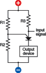
Figure 2-102.
This simple schematic shows how a PUT is used. R1 and R2 determine the voltage at the gate, which sets the threshold point for the input at the anode. Above the threshold, current flows from anode to cathode.