Make: Electronics (23 page)
Authors: Charles Platt

Experiment 10: Transistor Switching
You will need:
- AC adapter, breadboard, wire, and meter.
- LED. Quantity: 1.
- Resistors, various.
- Pushbutton, SPST. Quantity: 1.
- Transistor, 2N2222 or similar. Quantity: 1.
- Potentiometer, 1 megohm, linear.
A transistor can switch a flow of electricity, just like a relay. But it’s much more sensitive and versatile, as this first ultra-simple experiment will show.
We’ll start with the 2N2222 transistor, which is the most widely used semiconductor of all time (it was introduced by Motorola in 1962 and has been in production ever since).
First, you should get acquainted with the transistor. Because Motorola’s patents on the 2N2222 ran out long ago, any company can manufacture their own version of it. Some versions are packaged in a little piece of black plastic; others are enclosed in a little metal “can.” (See Figure 2-83.) Either way, it contains a piece of silicon divided into three sections known as the collector, the base, and the emitter. I’ll describe their function in more detail in a moment, but initially you just need to know that in this type of transistor, the collector receives current, the base controls it, and the emitter sends it out.
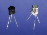
Figure 2-83.
A typical transistor is packaged either in a little metal can or a molded piece of black plastic. The manufacturer’s data sheet tells you the identities of the three wire leads, relative to the flat side of a black plastic transistor or the tab that sticks out of a metal-can transistor.
Use your breadboard to set up the circuit shown in Figure 2-85. Be careful to get the transistor the right way around! (See Figure 2-84.) For the three brands I have mentioned in the shopping list, the flat side should face right, if the transistor is packaged in black plastic, or the little tab should face toward the lower left, if the transistor is packaged in metal.
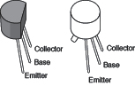
Figure 2-84.
The 2N2222 transistor may be packaged in either of these formats. Left: RadioShack or Fairchild. Right: STMicroelectronics (note the little tab sticking out at the lower-left side). If you use a different brand, you’ll have to check the manufacturer’s data sheet. Insert the transistor in your breadboard with the flat side facing right, as seen from above, or the tab pointing down and to the left, seen from above.
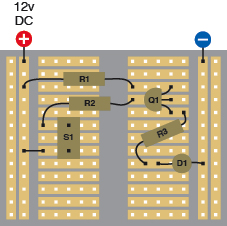
Figure 2-85.
The transistor blocks voltage that reaches it through R1. But when pushbutton S1 is pressed, this tells the transistor to allow current to pass through it. Note that transistors are always identified with letter Q in wiring diagrams and schematics.
S1: Pushbutton, momentary, OFF (ON)
R1: 180Ω
R2: 10K
R3: 680Ω
Q1: 2N2222 or similar
D1: LED
Initially, the LED should be dark. Now press the pushbutton and the LED should glow brightly. Electricity is following two paths here. Look at the schematic in Figure 2-86, which shows the same circuit more clearly. I’ve shown positive at the top and negative at the bottom (the way most schematics do it) because it helps to clarify the function of this particular circuit. If you view the schematic from the side, the similarity with the breadboard layout is easier to see.
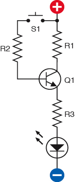
Figure 2-86.
This shows the same circuit as the breadboard diagram in Figure 2-85.
Through R1, voltage reaches the top pin (the collector) of the transistor. The transistor only lets a tiny trickle of it pass through, so the LED stays dark. When you press the button, voltage is also applied along a separate path, through R2 to the middle pin (the base) of the transistor. This tells the transistor to close its solid-state switch and allow current to flow out through its third pin (the emitter), and through R3, to the LED.
You can use your meter in volts DC mode to check the voltage at points in the circuit. Keep the negative probe from the meter touching the negative voltage source while you touch the positive probe to the top pin of the transistor, the middle pin, and the bottom pin. When you press the button, you should see the voltage change.
Fingertip Switching
Now here’s something more remarkable. Remove R2 and the pushbutton, and insert two short pieces of of wire as shown in Figure 2-87. The upper piece of wire connects with the positive voltage supply; the lower piece connects with the middle pin of the transistor (its base). Now touch the tip of your finger to the two wires. Once again, the LED should glow, although not as brightly as before. Lick the tip of your finger, try again, and the LED should glow more brightly.
 Never Use Two Hands
The fingertip switching demo is safe if the electricity passes just through your finger. You won’t even feel it, because it’s 12 volts DC from a power supply of 1 amp or less. But it’s not a good idea to put the finger of one hand on one wire, and the finger of your other hand on the other wire. This would allow the electricity to pass through your body. Although the chance of hurting yourself this way is extremely small,
you should never allow electricity to run through you from one hand to the other
. Also, when touching the wires, don’t allow them to penetrate your skin.
Your finger is conducting positive voltage to the base of the transistor. Even though your skin has a high resistance, the transistor still responds. It isn’t just switching the LED on and off; it is
amplifying the current
applied to its base. This is an essential concept:
a transistor amplifies any changes in current that you apply to its base
.
Check Figure 2-88 to see more clearly what’s happening.
If you studied the section “Background: Positive and negative” in
Chapter 1
, you learned that there is really no such thing as positive voltage. All we really have is negative voltage (created by the pressure of free electrons) and an absence of negative voltage (where there are fewer free electrons). But because the idea of a flow of electricity from positive to negative was so widely believed before the electron was discovered, and because the inner workings of a transistor involve “holes” which are an absence of electrons and can be thought of as positive, we can still pretend that electricity flows from positive to negative. See the following section, “Essentials: All about NPN and PNP transistors,” for more details.
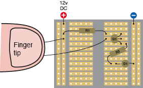
Figure 2-87
.
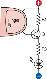
Figure 2-88.
These two diagrams show the same components as before, with a fingertip substituted for R2. Although only a trickle of voltage now reaches the base of the transistor, it’s enough to make the transistor respond.
Essentials
All about NPN and PNP transistors
A transistor is a semiconductor, meaning that sometimes it conducts electricity, and sometimes it doesn’t. Its internal resistance varies, depending on the power that you apply to its base.
NPN and PNP transistors are bipolar semiconductors. They contain two slightly different variants of silicon, and conduct using both polarities of carriers—holes and electrons.
The NPN type is a sandwich with P-type silicon in the middle, and the PNP type is a sandwich with N-type silicon in the middle. If you want to know more about this terminology, and the behavior of electrons when they try to cross an NP junction or a PN junction, you’ll have to read a separate source on this subject. It’s too technical for this book. All you need to remember is:
- All bipolar transistors have three connections: Collector, Base, and Emitter, abbreviated as C, B, and E on the manufacturer’s data sheet, which will identify the pins for you.
- NPN transistors are activated by
positive
voltage on the base relative to the emitter. - PNP transistors are activated by
negative
voltage on the base relative to the emitter.
In their passive state, both types block the flow of electricity between the collector and emitter, just like an SPST relay in which the contacts are normally open. (Actually a transistor allows a tiny bit of current known as “leakage.”)
You can think of a bipolar transistor as if it contains a little button inside, as shown in Figures 2-89 and 2-90. When the button is pressed, it allows a large current to flow. To press the button, you inject a much smaller current into the base by applying a small voltage to the base. In an NPN transistor, the control voltage is positive. In a PNP transistor, the control voltage is negative.
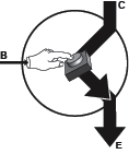
Figure 2-89.
You can think of a bipolar transistor as if it contains a button that can connect the collector and the emitter. In an NPN transistor, a small positive potential presses the button.
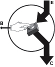
Figure 2-90.
In a PNP transistor, a small negative potential has the same effect. The arrows point in the direction of “positive current flow.”
NPN transistor basics
- To start the flow of current from collector to emitter, apply a relatively positive voltage to the base.
- In the schematic symbol, the arrow points from base to emitter and shows the direction of positive current.
- The base must be at least 0.6 volts “more positive” than the emitter, to start the flow.
- The collector must be “more positive” than the emitter.
PNP transistor basics
- To start the flow of current from emitter to collector, apply a relatively negative voltage to the base.
- In the schematic symbol, the arrow points from emitter to base and shows the direction of positive current.
- The base must be at least 0.6 volts “more negative” than the emitter, to start the flow.
- The emitter must be “more positive” than the collector.