Make: Electronics (48 page)
Authors: Charles Platt

Theory
Inside the 555 timer: astable mode (continued)
R1 now controls the charge time on its own, while R2 controls the discharge time. The formula for calculating the frequency is now:
Frequency = 1.44 / ((R1 + R2) × C1) or Frequency = 1.4 / ((R1 + R2) × C1)
If you set R1 = R2, you should get almost equal on/off cycles (“almost” because the diode itself imposes a small internal voltage drop of about 0.6V). The exact value depends primarily on the manufacturing process used to make the diode.
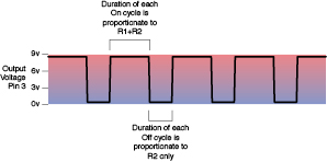
Figure 4-24.
In its usual astable configuration, the timer charges a capacitor through R1+R2 and discharges the capacitor through R2 only. Therefore its output on cycles are longer than its output off cycles.
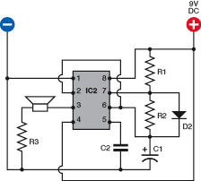
Figure 4-25.
This is a modification of the schematic shown in Figure 4-22. By adding a diode to a 555 timer running in astable mode, we eliminate R2 from the charging cycle of capacitor C1. Now we can adjust the output on cycle with the value of R1, and the output off cycle with the value of R2, so that the on and off durations are independent of each other.
Fundamentals
The following table shows 555 timer frequency in astable mode:
- Frequency is in pulses per second, rounded to two figures.
- The horizontal scale shows common resistor values for R2.
- The vertical scale shows common capacitor values for C1. Resistor R1 is assumed to be 1K.
- Resistor R1 is assumed to be 1K.
To calculate a different frequency: double R2, add the product to R1, multiply the sum by C1, and divide the result into 1440. Like this:
Frequency = 1440 / ( (R1 + 2R2) × C1) cycles per second
In this formula, R1 and R2 are in kilohms, C1 is in microfarads, and the frequency is in hertz (cycles per second). Note that the frequency is measured from the start of one pulse to the start of the next. The duration of each pulse is not the same as the length of time between each pulse. This issue is discussed in the previous section.
47 µF | 10 | 5.7 | 3.0 | 1.5 | 0.7 | 0.3 | 0.2 | 0.1 | ||
22 µF | 22 | 12.0 | 6.3 | 3.1 | 1.5 | 0.7 | 0.3 | 0.2 | 0.1 | |
10 µF | 48 | 27.0 | 14.0 | 6.9 | 3.2 | 1.5 | 0.7 | 0.3 | 0.2 | 0.1 |
04.7 µF | 100 | 57.0 | 30.0 | 15.0 | 6.8 | 3.2 | 1.5 | 0.7 | 0.3 | 0.2 |
02.2 µF | 220 | 120.0 | 63.0 | 31.0 | 15.0 | 6.9 | 3.3 | 1.5 | 0.7 | 0.3 |
01.0 µF | 480 | 270.0 | 140.0 | 69.0 | 32.0 | 15.0 | 7.2 | 3.3 | 1.5 | 0.7 |
00.47 µF | 1,000 | 570.0 | 300.0 | 150.0 | 68.0 | 32.0 | 15.0 | 7.0 | 3.3 | 1.5 |
00.22 µF | 2,200 | 1,200.0 | 630.0 | 310.0 | 150.0 | 69.0 | 33.0 | 15.0 | 7.0 | 3.3 |
00.1 µF | 4,800 | 2,700.0 | 1,400.0 | 690.0 | 320.0 | 150.0 | 72.0 | 33.0 | 15.0 | 7.2 |
00.047 µF | 10,000 | 5,700.0 | 3,000.0 | 1,500.0 | 680.0 | 320.0 | 150.0 | 70.0 | 33.0 | 15.0 |
00.022 µF | 22,000 | 12,000.0 | 6,300.0 | 3,100.0 | 1,500.0 | 690.0 | 330.0 | 150.0 | 70.0 | 33.0 |
00.01 µF | 48,000 | 27,000.0 | 14,000.0 | 6,900.0 | 3,200.0 | 1,500.0 | 720.0 | 330.0 | 150.0 | 72.0 |
1K | 2K2 | 4K7 | 10K | 22K | 47K | 100K | 220K | 470K | 1M |
Astable Modifications
In the circuits shown in Figures 4-22 or 4-25, if you substitute a 100K potentiometer for R2, you can adjust the frequency up and down by turning the shaft.
Another option is to “tune” the timer by using pin 5, the control, as shown in the Figure 4-26. Disconnect the capacitor that was attached to that pin and substitute the series of resistors shown. R9 and R11 are both 1K resistors, either side of R10, which is a 100K potentiometer. They ensure that pin 5 always has at least 1K between it and the positive and negative sides of the power supply. Connecting it directly to the power supply won’t damage the timer, but will prevent it from generating audible tones. As you turn the potentiometer to and fro, the frequency will vary over a wide range. If you want to generate a very specific frequency, a trimmer potentiometer can be used instead.
A primary advantage of using pin 5 to adjust frequency is that you can control it remotely. Take the output from pin 3 of another 555 timer running slowly in astable mode, and pipe it through a 2K2 resistor to pin 5. Now you get a two-tone siren effect, as one timer controls the other. If, in addition, you add a 100 µF capacitor between pin 5 and ground, the charging and discharging of the capacitor will make the tone slide up and down instead of switching abruptly. I’ll describe this in more detail shortly. This leads me to the whole topic of one chip controlling another chip, which will be our last variation on this experiment.
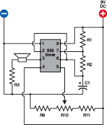
Figure 4-26.
The control (pin 5) is seldom used but can be useful. Varying the voltage on it will adjust the speed of the timer. This circuit enables you to test the behavior of it. Component values:
R1: 1K
R2: 10K
R3: 100 ohms
R9, R11: 1K
R10: 100K linear potentiometer
C1: 0.047 µF
Chaining Chips
Generally speaking, chips are designed so that they can talk to each other. The 555 couldn’t be easier in this respect:
- Pin 3, the output, from one 555 can be connected directly to pin 2, the trigger, of a second 555.
- Alternatively, the output can be sufficient to provide power to pin 8 of a second 555.
- The output is appropriate to control or power other types of chips too.
Figure 4-27 shows these options.
When the output from the first 555 goes high, it is about 70 to 80% of its supply voltage. In other words, when you’re using a 9V supply, the high output voltage is at least 6 volts. This is still above the minimum of 5V that the second chip needs to trigger its comparator, so there’s no problem.
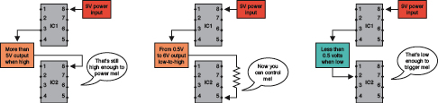
Figure 4-27.
Three ways to chain 555 timers together. The output of IC1 can power a second timer, or adjust its control voltage, or activate its trigger pin.