Make: Electronics (49 page)
Authors: Charles Platt

You can chain together the two 555 timers that you already have on your breadboard. Figure 4-28 shows how to connect the two circuits that were shown previously in Figures 4-15 and 4-22. Run a wire from pin 3 (the output) of the first chip to pin 8 (the positive power supply) of the second chip, and disconnect the existing wire connecting pin 8 to your power supply. The new wire is shown in red. Now when you press the button to activate the first chip, its output powers the second chip.
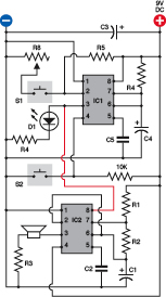
Figure 4-28.
You can combine the two circuits shown in Figures 4-15 and 4-22 simply by disconnecting the wire that provides power to pin 8 of the second timer, and running a substitute wire (shown in red).
You can also use the output from one chip to trigger another (i.e., you can connect pin 3 from the first chip to pin 2 of the second). When the output from the first chip is low, it’s less than half a volt. This is well below the threshold that the second chip requires to be activated. Why would you want to do this? Well, you might want to have both timers running in monostable mode, so that the end of a high pulse from the first one triggers the start of a high pulse in the second one. In fact, you could chain together as many timers as you like in this way, with the last one feeding back and triggering the first one, and they could flash a series of LEDs in sequence, like Christmas lights. Figure 4-29 shows how four timers could be linked this way, in a configuration that would occupy minimal space (and would be wired point-to-point on perforated board, not on breadboard-format board). Each of the outputs numbered 1 through 4 would have about enough power to run maybe 10 LEDs, if you used relatively high load resistors to limit their current.
Figure 4-29.
Four 555 timers, chained together in a circle, can flash a series of four sets of LEDs in sequence, like Christmas lights or a movie marquee.
Incidentally, you can reduce the chip count (the number of chips) by using two 556 timers instead of four 555 timers. The 556 contains a pair of 555 timers in one package. But because you have to make the same number of external connections (other than the power supply), I haven’t bothered to use this variant.
You can even get a 558 timer that contains four 555 circuits, all preset to function in astable mode. I decided not to use this chip, because its output behaves differently from a normal 555 timer. But you can buy a 558 timer and play with it if you wish. It is ideal for doing the “chain of four timers” that I suggested previously. The data sheet even suggests this.
Lastly, going back to the idea of modifying the frequency of a 555 timer in astable mode, you can chain two timers, as shown in Figure 4-30. The red wire shows the connection from the output of the first timer to the control pin of the second. The first timer has now been rewired in astable mode, so that it creates an oscillating on/off output around four times per second. This output flashes the LED (to give you a visual check of what’s going on) and feeds through R7 to the control pin of the second timer.
But C2 is a large capacitor, which takes time to charge through R7. While this happens, the voltage detected by pin 5 slowly rises, so that the tone generated by IC2 gradually lowers in pitch. Then IC1 reaches the end of its on cycle and switches itself off, at which point C2 discharges and the pitch of the sound generated by IC2 falls again.
You can tweak this circuit to create all kinds of sounds, much more controllably then when you were using PUT transistors to do the same kind of thing. Here are some options to try:
- Double or halve the value of C2.
- Omit C2 completely, and experiment with the value of R7.
- Substitute a 10K potentiometer for R7.
- Change C4 to increase or decrease the cycle time of IC1.
- Halve the value of R5 while doubling the value of C4, so that the cycle time of IC1 stays about the same, but the On time becomes significantly longer than the Off time.
- Change the supply voltage in the circuit from 9 volts to 6 volts or 12 volts.
Remember, you can’t damage a 555 timer by making changes of this kind. Just make sure that the negative side of your power supply goes to pin 1 and the positive side to pin 8.
Figure 4-30.
When both timers are astable, but IC1 runs much more slowly than IC2, the output from IC1 can be used to modulate the tone generated by IC2. Note that as this is a substantial modification to the previous schematics, several components have been relabeled. To avoid errors, you may need to remove the old circuit from your breadboard and build this version from scratch. Try these values initially:
R1, R4, R6, R7: 1K
R2, R5: 10K
R3: 100 ohms
C1: 0.047 µF
C2, C3: 100 µF
C4: 68 µF
C5: 0.1 µF
Experiment 18: Reaction Timer
Because the 555 can easily run at thousands of cycles per second, we can use it to measure human reactions. You can compete with friends to see who has the fastest response—and note how your response changes depending on your mood, the time of day, or how much sleep you got last night.
Before going any further, I have to warn you that this circuit will have more connections than others you’ve tackled so far. It’s not conceptually difficult, but requires a lot of wiring, and will only just fit on a breadboard that has 63 rows of holes. Still, we can build it in a series of phases, which should help you to detect any wiring errors as you go.
You will need:
- 4026 chip. Quantity: 4 (really you need only 3, but get another one in case you damage the others).
- 555 timers. Quantity: 3.
- Tactile switches (SPST momentary switches). Quantity: 3.
- Three numeric LEDs, or one 3-digit LED display (see the shopping list at the beginning of this chapter). Quantity: 1.
- Breadboard, resistors, capacitors, and meter, as usual.
Step 1: Display
You can use three separate LED numerals for this project, but I suggest that you buy the Kingbright BC56-11EWA on the shopping list at the beginning of this chapter. It contains three numerals in one big package.
You should be able to plug it into your breadboard, straddling the center channel. Put it all the way down at the bottom of the breadboard, as shown in Figure 4-31. Don’t put any other components on the breadboard yet.
Now set your power supply to 9 volts, and apply the
negative
side of it to the row of holes running up the breadboard on the
righthand
side. Insert a 1K resistor between that negative supply and each of pins 18, 19, and 26 of the Kingbright display, which are the “common cathode,” meaning the negative connection shared by each set of LED segments in the display. (The pin numbers of the chip are shown in Figure 4-33. If you’re using another model of display, you’ll have to consult a data sheet to find which pin(s) are designed to receive negative voltage.)
Switch on the power supply and touch the free end of the positive wire to each row of holes serving the display on its left and right sides. You should see each segment light up, as shown in Figure 4-31.
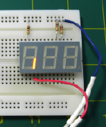
Figure 4-31.
After putting a 1K resistor between the common cathode of the display and the negative supply voltage, you can use the positive supply voltage to illuminate each segment in turn.
Each numeral from 0 to 9 is represented by a group of these segments. The segments are always identified with lowercase letters
a
through
g
, as shown in Figure 4-32. In addition, there is often a decimal point, and although we won’t be using it, I’ve identified it with the letter
h
.
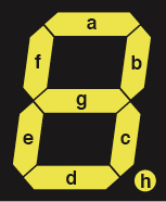
Figure 4-32.
The most basic and common digital numeral consists of seven LED segments identified by letters, as shown here, plus an optional decimal point.
Check Figure 4-33 showing the Kingbright display, and you’ll see I have annotated each pin with its function. You can step down the display with the positive wire from your power supply, making sure that each pin lights an appropriate segment.
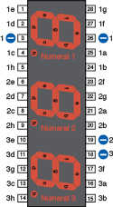
Figure 4-33.
This Kingbright unit incorporates three seven-segment numeric displays in one package, and can be driven by three chained 4026 decade counters. The pin numbers are shown close to the chip. Segments a through g of numeral 1 are identified as 1a through 1g. Segments a through g of numeral 2 are identified as 2a through 2g. Segments a through g of numeral 3 are identified as 3a through 3g.