Make: Electronics (38 page)
Authors: Charles Platt

However, I will address one final issue: how long will this gadget continue flashing?
If you check the following section “Essentials: Battery life,” you’ll find that a regular alkaline 9-volt battery should keep the LED flashing for about 50 hours.
ESSENTIALS
Battery life
Any time you finish a circuit that you intend to run from a battery, you’ll want to calculate the likely battery life. This is easily done, because manufacturers rate their batteries according to the “ampere hours” they can deliver. Keep the following in mind:
- The abbreviation for amp-hours is Ah, sometimes printed as AH. Milliampere-hours are abbreviated mAh.
- The rating of a battery in amp-hours is equal to the current, in amps, multiplied by the number of hours that the battery can deliver it.
Thus, in theory 1 amp-hour can mean 1 amp for 1 hour, or 0.1 amp for 10 hours, or 0.01 amp for 100 hours—and so on. In reality, it’s not as simple as this, because the chemicals inside a battery become depleted more quickly when you draw a heavy current, especially if the battery gets hot. You have to stay within limits that are appropriate to the size of the battery.
For instance, if a small battery is rated for 0.5 amp-hours, you can’t expect to draw 30 amperes from it for 1 minute. But you should be able to get 0.005 amps (i.e., 5 milliamps) for 100 hours without any trouble. Remember, though, that the voltage delivered by a battery will be greater than its rated voltage when the battery is fresh, and will diminish below its rated voltage while the battery is delivering power.
According to some test data that I trust (I think they are a little more realistic than the estimates supplied by battery manufacturers), here are some numbers for typical batteries:
- Typical 9 volt alkaline battery: 0.3 amp-hours, while delivering 100 mA.
- Typical AA size, 1.5-volt alkaline battery: 2.2 amp-hours, while delivering 100 mA.
- Rechargeable nickel-metal hydride battery: about twice the endurance of a comparably sized alkaline battery.
- Lithium battery: maybe three times the endurance of an alkaline battery.
Background
Maddened by measurement
Throughout most of this book, I’ve mostly used measurements in inches, although sometimes I’ve digressed into the metric system, as when referring to “5-mm LEDs.” This isn’t inconsistency on my part; it reflects the conflicted state of the electronics industry, where you’ll find inches and millimeters both in daily use, often in the very same data sheet.
The United States is the only major nation still using the old system of units that originated in England. (The other two holdouts are Liberia and Myanmar, according to the CIA’s
World Factbook
.) Still, the United States has led many advances in electronics, especially the development of silicon chips, which have contacts spaced 1/10 inch apart. These standards became firmly established, and show no sign of disappearing.
To complicate matters further, even in the United States, you can encounter two incompatible systems for expressing fractions of an inch. Drill bits, for instance, are measured in multiples of 1/64 inch, while metal thicknesses may be measured in decimals such as 0.06 inch (which is approximately 1/16 inch).
The metric system is not necessarily more rational than the U.S. system. Originally, when the metric system was formally introduced in 1875, the meter was defined as being 1/10,000,000 of the distance between the North Pole and the equator, along a line passing through Paris—a quixotic, Francocentric conceit. Since then, the meter has been redefined three times, in a series of efforts to achieve greater accuracy in scientific applications.
As for the usefulness of a 10-based system, moving a decimal point is certainly simpler than doing calculations in 64ths of an inch, but the only reason we count in tens is because we happen to have evolved with that number of digits on our hands. A 12-based system would really be more convenient, as numbers would be evenly divisible by 2 and 3.
As we’re stuck with the whimsical aspects of length measurement, I’ve created the charts in Figures 3-83 and 3-84 to assist you in going from one system to another. From these you will see that when you need to drill a hole for a 5 mm LED, a 3/16-inch drill bit is about right. (In fact, it results in a better, tighter fit than if you drill an actual 5 mm hole.)

Figure 3-83.
Because units of measurement are not standardized in electronics, conversion is often necessary. The chart on the right is a 5x magnification of the bottom section of the chart on the left.

Figure 3-84.
This chart allows conversion between hundredths of an inch, conventional U. S. fractions of an inch, and fractions expressed in thousandths of an inch.
Experiment 15: Intrusion Alarm Revisited
Time now to add some of the enhancements to the intrusion alarm that I discussed at the end of
Experiment 11
. I’m going to show you how the alarm can be triggered if you install various detectors on windows and doors in your home. I’ll also show how the alarm can be wired so that it locks itself on and continues to make noise even after a door or window is reclosed.
This experiment will demonstrate the procedure for transferring a project from a breadboard to a piece of perforated board that has copper connections laid out identically to the ones inside the breadboard, as shown earlier in Figure 3-72. And you’ll mount the finished circuit in a project box with switches and connectors on the front.
When all is said and done, you’ll be ready for wholesale circuit building. The explanations in the rest of this book will get gradually briefer, and the pace will increase.
You will need:
- 15-watt pencil-type soldering iron
- Thin solder (0.022 inches or similar)
- Wire strippers and cutters
- Perforated board etched with copper in a breadboard layout
- Small vise or clamp to hold your perforated board
- The same components that you used in
Experiment 11
, plus: - 2N2222 NPN transistor. Quantity: 1.
- DPDT relay. Quantity: 1.
- SPDT toggle switch. Quantity: 1.
- 1N4001 diode. Quantity: 1.
- Red and green 5mm LEDs. Quantity: 1 each.
- Project box, 6 × 3 × 2 inches.
- Power jack, type N, and matching power socket, type N.
- Binding posts.
- Stranded 22-gauge wire, three different colors.
- Magnetic sensor switches, sufficient for your home.
- Alarm network wiring, sufficient for your home.
Magnetic Sensor Switches
A typical alarm sensor switch consists of two modules: the magnetic module and the switch module, as shown in Figures 3-85 and 3-86. The magnetic module contains a permanent magnet, and nothing else. The switch module contains a “reed switch,” which makes or breaks a connection (like a contact inside a relay) under the influence of the magnet. When you bring the magnetic module close to the switch module, you may faintly hear the reed switch click as it flips from one state to the other.
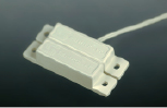
Figure 3-85.
In this simple alarm sensor switch, the lower module contains a magnet, which opens and closes a reed switch sealed into the upper module.
Like all switches, reed switches can be normally open or normally closed. For this project, you want the kind of switch that is normally open, and closes when the magnetic module is close to it.
Attach the magnetic module to the moving part of a door or window, and attach the switch module to the window frame or door frame. When the window or door is closed, the magnetic module is almost touching the switch module. The magnet keeps the switch closed until the door or window is opened, at which point the switch opens.
The only question is: how do we use this component to trigger our alarm? As long as a small current flows through all our magnetic sensor switches, the alarm should be off, but if the flow of current stops, the alarm should switch on.
We could use a relay that is “always on” while the alarm is armed. When the circuit is interrupted, the relay relaxes and its other pair of contacts closes, which could power up the alarm noisemaker.
But I don’t like this idea. Relays take significant power, and they can get hot. Most of them are not designed to be kept “always-on.” I’d prefer to handle the task using a transistor.
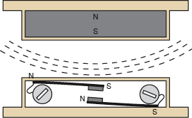
Figure 3-86.
This cutaway diagram shows a reed switch (bottom) and the magnet that activates it (top), inside an alarm sensor. The switch contains two flexible magnetized strips, the upper one with its south pole adjacent to an electrical contact, the lower one with its north pole adjacent to an electrical contact. When the south pole of the magnet approaches the switch, the magnetic force (shown as dashed lines) repels the south contact and attracts the north contact, causing them to snap together. Two screws on the outside of the casing are connected with the strips inside.
A Break-to-Make Transistor Circuit
First, recall how an NPN transistor works. When the base is not sufficiently positive, the transistor blocks current between its collector and emitter, but when the base is relatively positive, the transistor passes current.
Take a look at the schematic in Figure 3-87, which is built around our old friend the 2N2222 NPN transistor. When the switch is closed, it connects the base of the transistor to the negative side of the power supply through a 1K resistor. At the same time, the base is connected with the positive side of the power supply through a 10K resistor. Because of the difference in resistances and the relatively high turn-on voltage for the LED, the base is forced below its turn-on threshold, and as a result, the transistor will not pass much current. The LED will glow dimly at best.