Make: Electronics (36 page)
Authors: Charles Platt

Experiment 14: A Pulsing Glow
You will need:
- Breadboard
- 15-watt pencil-type soldering iron
- Thin solder (0.022 inches or similar)
- Wire strippers and cutters
- Plain perforated board (no copper etching necessary)
- Small vise or clamp to hold your perforated board
- Resistors, various
- Capacitors, electrolytic, 100 µF and 220 µF, one of each
- Red LED, 5 mm, rated for 2 volts approximately
- 2N6027 programmable unijunction transistor
Your first circuit using a PUT was a slow-speed oscillator that made an LED flash about twice each second. The flashes looked very “electronic,” by which I mean that the LED blinked on and off without a gradual transition between each state. I’m wondering if we can modify this circuit to make the LED pulse in a more gentle, interesting way, like the warning light on an Apple MacBook when it’s in “sleep” mode. I’m thinking that something of this sort might be wearable as an ornament, if it’s small enough and elegant enough.
I’m also thinking that this first soldering project will serve three purposes. It will test and refine your skill at joining wires together, will teach you point-to-point wiring with perfboard, and will give you some additional insight into the way that capacitors can be used to adjust timing.
Look back at the original circuit in
Experiment 11
, on
page 82
. Refresh your memory about the way it worked. The capacitor charges through a resistor until it has enough voltage to overcome the internal resistance in the PUT. Then the capacitor discharges through the PUT and flashes the LED.
If you drew a graph of the light coming out of the LED, it would be a thin, square-shaped pulse, as shown in Figure 3-73. How can we fill it out to make it more like the curve in Figure 3-74, so that the LED fades gently on and off, like a heartbeat?
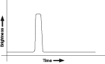
Figure 3-73
.
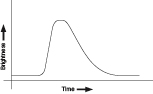
Figure 3-74.
The original PUT oscillator circuit in
Experiment 11
made the LED emit sharp, short flashes. The upper graph shows what we might find if we measured light output over time. The second graph shows a gentler onset to each flash, followed by a slow fade-out. Capacitors can be used to create this effect.
One thing is obvious: the LED is going to be emitting a greater total amount of light in each cycle. Therefore, it’s going to need more power. This means that C1, in Figure 3-75, must be a larger capacitor.
When we have a larger capacitor, it takes longer to charge. To keep the flashes reasonably frequent, we’ll need a lower-value resistor for R1 to charge the capacitor quickly enough. In addition, reducing the values of R2 and R3 will program the PUT to allow a longer pulse.
Most important, I want to discharge the capacitor through a resistor to make the onset of the pulse gradual instead of sudden. Remember, when you have a resistor in series with a capacitor, the capacitor not only charges more slowly, but discharges more slowly.
Figure 3-75 shows these features. Compare it with Figure 2-103 on
page 85
. R1 is now 33K instead of 470K. R2 and R3 are reduced to 1K. R4 also is 1K, so that the capacitor takes longer to discharge. And C1 is now 100 µF instead of 2.2 µF.
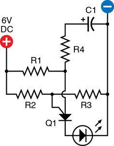
Figure 3-75.
The first step toward creating a gentler flashing effect is to use a larger capacitor for C1 and discharge it through a resistor, R4. Lower-value resistors are necessary to charge the capacitor rapidly enough.
R1: 33K
R2: 1K
R3: 1K
R4: 1K
C1: 100 µF electrolytic
Q1: 2N6027
Assemble this circuit on a breadboard, and compare the results when you include R4 or bypass it with a plain piece of jumper wire. It softens the pulse a bit, but we can work on it some more. On the output side of the PUT, we can add another capacitor. This will charge itself when the pulse comes out of the PUT, and then discharge itself gradually through another resistor, so that the light from the LED dies away more slowly.
Figure 3-76 shows the setup. C2 is large—220 µF—so it sucks up the pulse that comes out of the PUT, and then gradually releases it through 330Ω resistor R5 and the LED. You’ll see that the LED behaves differently now, fading out inside of blinking off. But the resistances that I’ve added have dimmed the LED, and to brighten it, you should increase the power supply from 6 volts to 9 volts.
Remember that a capacitor imposes a smoothing effect only if one side of it is grounded to the negative side of the power supply. The presence of the negative charge on that side of the capacitor attracts the positive pulse to the other side.
I like the look of this heartbeat effect. I can imagine a piece of wearable electronic jewelry that pulses in this sensual way, very different from the hard-edged, sharp-on-and-off of a simple oscillator circuit. The only question is whether we can squeeze the components into a package that is small enough to wear.
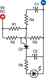
Figure 3-76.
The second step toward a gentler flashing effect is to add another capacitor, C2, which charges quickly with each pulse and then discharges slowly through R5 and the LED below it.
Same components as before, plus:
R5: 330Ω
C2: 220 µF electrolytic
Power supply increased to 9 volts
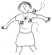
Figure 3-77.
On a dark night in a rural area, the heartbeat flasher may be attractive in unexpected ways.
Resizing the Circuit
The first step is to look at the physical components and imagine how to fit them into a small space. Figure 3-78 shows a 3D view of a compact arrangement. Check this carefully, tracing all the paths through the circuit, and you’ll see that it’s the same as the schematic. The trouble is that if we solder the components together like this, they won’t have much strength. All the little wires can bend easily, and there’s no easy way to mount the circuit in something or on something.
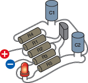
Figure 3-78.
This layout of components replicates their connections in the schematic diagram while squeezing them into a minimal amount of space.
The answer is to put it on a substrate, which is one of those terms that people in the electronics field like to use, perhaps because it sounds more technical than “perfboard.” But perforated board is what we need, and Figure 3-79 shows the components transferred onto a piece of board measuring just 1 inch by 0.8 inch.
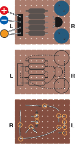
Figure 3-79.
Perforated board can be used to support the layout of components. Their leads are soldered together under the board to create the circuit. The middle diagram shows the wires under the board as dashed lines. The bottom diagram shows the board from underneath, flipped left to right. Orange circles indicate where solder joints will be necessary.
The center version of this diagram uses dotted lines to show how the components will be connected with each other underneath the board. Mostly the leads that stick out from underneath the components will be long enough to make these connections.