Make: Electronics (39 page)
Authors: Charles Platt

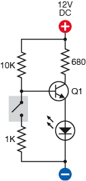
Figure 3-87.
In this demonstration circuit, when the switch is opened, it interrupts negative voltage to the base of the transistor, causing the transistor to lower its resistance, allowing current to reach the LED. Thus, when the switch is turned off, it turns on the LED.
Now what happens when the switch is opened? The base of the transistor loses its negative power supply and has only its positive power supply. It becomes much more positive, above the turn-on threshold for the transistor, which tells the transistor to lower its resistance and pass more current. The LED now glows brightly. Thus, when the switch is turned off and breaks the connection, the LED is turned on.
This seems to be what we want. Imagine a whole series of switches instead of just one switch, as shown in Figure 3-88. The circuit will still work the same way, even if the switches are scattered all over your home, because the resistance in the wires connecting the switches will be trivial compared with the resistance of the 1K resistor.
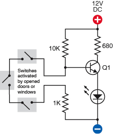
Figure 3-88.
A network of switches, wired in series, can be substituted for the single switch in Figure 3-87. Now any one switch will break continuity and trigger the transistor.
I have shown the switches open, because that’s the way the schematic for a switch is drawn, but imagine them all closed. The base of the transistor will now be supplied through the long piece of wire connecting all the closed switches, and the LED will stay dark. Now if just one switch is opened, or if anyone tampers with the wire linking them, the base of the transistor loses its connection to negative power, at which point the transistor conducts power and the LED lights up.
While all the switches remain closed, the circuit is drawing very little current—probably about 1.1 mA. So you could run it from a typical 12-volt alarm battery.
Now suppose we swap out the LED and put a relay in there instead, as shown in Figure 3-89. I don’t mind using a relay in this location, because the relay will not be “always on.” It will normally be off, and will draw power only when the alarm is triggered.
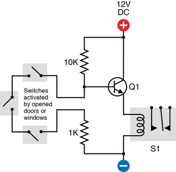
Figure 3-89.
If the LED and 680Ω resistor shown in are removed, and a relay takes their place, the relay will be activated when any switch in the sensor network is opened.
Try one of the 12-volt relays that you used previously. You should find that when you open the switch, the relay is energized. When you close the switch, the relay goes back to sleep. Note that I eliminated the 680Ω resistor from the circuit, because the relay doesn’t need any protection from the 12-volt power supply.
Self-Locking Relay
There’s only one remaining problem: we want the alarm to continue making noise even after someone who has opened a door or window closes it again quickly. In other words, when the relay is activated, it must lock itself on.
One way to do this would be by using a latching relay. The only problem is that we would then need another piece of circuitry to unlatch it. I prefer to show you how you can make any relay keep itself switched on after it has received just one jolt of power. This idea will be useful to you later in the book as well.
The secret is to supply power to the relay coil through the two contacts inside the relay that are normally open. (Note that this is exactly opposite to the relay oscillator, which supplied power to its coil through the contacts that were normally closed. That setup caused the relay to switch itself off almost as soon as it switched itself on. This setup causes the relay to keep itself switched on, as soon as it has been activated.)
In Figure 3-90, the four schematics illustrate this. You can imagine them as being like frames in a movie, photographed microseconds apart. In the first picture, the switch is open, the relay is not energized, and nothing is happening. In the second, the switch has been closed to energize the coil. In the third, the coil has pulled the contact inside the relay, so that power now reaches the coil via two paths. In the fourth, the switch has been opened, but the relay is still powering its own coil through its contacts. It will remain locked in this state until the power is disconnected.
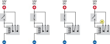
Figure 3-90.
This sequence of schematics shows the events that occur when a relay is energized. Initially, the switch is open. Then the switch is closed, activating the relay. The relay then powers itself through its own internal contacts. The relay remains energized even after the switch is opened again. Power switched by the relay can be taken from the circuit at point A.
All we need to do, to make use of this idea, is to substitute the transistor for the on/off switch, and tap into the circuit at point A, running a wire from there to the noisemaking module.
Figure 3-91 shows how that would work. When the transistor is activated by any of the network of sensor switches, as previously explained, the transistor conducts power to the relay. The relay locks itself on, and the transistor becomes irrelevant.
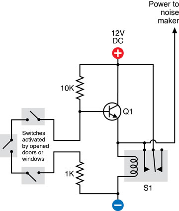
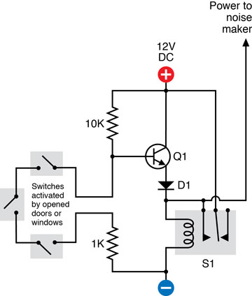
Figure 3-91.
The self-locking relay depicted in Figure 3-90 has been incorporated in the alarm circuit, so that if any switch in the network is opened, the relay will continue to power the noise maker even if the switch is closed again.
Because I’ve been adding pieces to the original alarm noisemaker circuit, I’ve updated the block diagram from Figure 2-112 to show that we can still break this down into modules with simple functions. The revised diagram is shown in Figure 3-92.
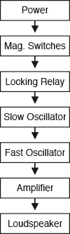
Figure 3-92.
This block diagram previously shown in Figure 2-112 on
page 90
has been updated to include the magnetic-switch network and locking-relay control system.
Blocking Bad Voltage
One little problem remains: in the new version of the circuit, if the transistor goes off while the relay is still on, current from the relay can flow back up the wire to the emitter of the transistor, where it will try to flow backward through the transistor to the base, which is “more negative,” as it is linked through all the magnetic switches and the 1K resistor to the negative side of the power supply.
Applying power backward through a transistor is not a nice thing to do. Therefore the final schematic in this series shows one more component, which you have not seen before: a diode, labeled D1. See Figure 3-93. The diode looks like the heart of an LED, and indeed, that’s pretty much what it is, although some diodes are much more robust. It allows electricity to flow in only one direction, from positive to negative, as shown by its arrow symbol. If current tries to flow in the opposite direction, the diode blocks it. The only price you pay for this service is that the diode imposes a small voltage drop on electricity flowing in the “OK” direction.
So now, positive flow can pass from the transistor, through the diode, to the relay coil, to get things started. The relay then supplies itself with power, but the diode prevents the positive voltage from getting back into the transistor the wrong way.
Perhaps a more elegant solution to the problem is to connect the NO (normally open) leg of the relay via a 10k resistor to the base connection. When the relay is not energized, the NO leg is inert and simply behaves as a parasitic capacitance on the node. When the relay becomes energized, the NO leg shunts +12V through the common terminal via a 10k resistor into the base of the transistor. In this circuit configuration, the transistor is never exposed to a potentially harmful voltage and you are not depending on leakage currents of non-ideal elements to protect devices.
However, I needed an opportunity to introduce you to the concept of diodes. You can check the following section “Essentials: All about diodes” to learn more.