Make: Electronics (40 page)
Authors: Charles Platt

Figure 3-93.
Diode D1 has been added to protect the emitter of Q1 from positive voltage when the relay is energized.
Essentials
All about diodes
A diode is a very early type of semiconductor. It allows electricity to flow in one direction, but blocks it in the opposite direction. (A light-emitting diode is a much more recent invention.) Like an LED, a diode can be damaged by reversing the voltage and applying excessive power, but most diodes generally have a much greater tolerance for this than LEDs. The end of the diode that blocks positive voltage is always marked, usually with a circular band, while the other end remains unmarked. Diodes are especially useful in logic circuits, and can also convert alternating current (AC) into direct current (DC).
A Zener diode is a special type that we won’t be using in this book. It blocks current completely in one direction, and also blocks it in the other direction until a threshold voltage is reached—much like a PUT.
Signal diodes are available for various different voltages and wattages. The 1N4001 diode that I recommend for the alarm activation circuit is capable of handling a much greater load at a much higher voltage, but I used it because it has a low internal resistance. I wanted the diode to impose a minimal voltage drop, so that the relay would receive as much voltage as possible.
It’s good practice to use diodes at less than their rated capacity. Like any semiconductor, they can overheat and burn out if they are subjected to mistreatment.
The schematic symbol for a diode has only one significant variant: sometimes the triangle is outlined instead of filled solid black (see Figure 3-94).

Figure 3-94.
Either of these schematic symbols may be used to represent a diode, but the one on the right is more common than the one on the left.
Completing the Breadboard Alarm Circuit
It’s time now to breadboard the control circuit for your alarm noisemaker. Figure 3-95 shows how this can be done. I am assuming that you still have the noisemaker, which functions as before. I’m assuming that you still have its relevant components mounted on the top half of the breadboard. To save space, I’m just going to show the additional components mounted on the bottom half of the same breadboard.
It’s important to remember that you are not supplying power directly to the left and right “rails” on the breadboard anymore; you are supplying power to the relay-transistor section, and when the relay closes its contacts, the
relay
supplies power to the rails. These then feed the power up to the top half of the breadboard. So disconnect your power supply from the breadboard rails and reconnect it as shown in Figure 3-95.
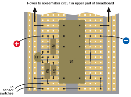
Figure 3-95.
The schematic that was developed in the previous pages can be emulated with components on a breadboard, as shown here. S1 is a DPDT relay. Wires to the sensor switch network and to the power supply must be added where shown.
Because it’s a double-pole relay, I am using it to switch negative as well as positive. This means that when the relay contacts are open, the noisemaking section of the circuit is completely isolated from the rest of the world.
The breadboarded relay circuit is exactly the same as the schematic in Figure 3-93. The components have just been rearranged and squeezed together so that they will fit alongside the relay. Two wires at the lower-left corner go to the network of magnetic sensor switches that will trip the alarm; for testing purposes, you can just hold the stripped ends of these two wires together to simulate all the switches being closed, and separate the wires to simulate a switch opening.
Two more wires bring power to the breadboard on either side of the relay. This is where you should connect your power supply during testing. The output from the relay, through its top pair of contacts, is connected with the rails of the breadboard by a little jumper wire at top left, and another at top right. Don’t forget to include them! One more little wire at the lower-left corner (easily overlooked) connects the lefthand side rail to the lefthand coil terminal of the relay, so that when the relay is powering the noisemaker circuit, it powers itself as well.
When you mount the diode, remember that the end of it that is marked with a band around it is the end that blocks positive current. In this circuit, that’s the lower end of the diode.
Try it to make sure that it works. Short the sensor wires together and then apply power. The alarm should remain silent. You can use your meter to check that no voltage exists between the side rails. Now separate the sensor wires, and the relay should click, supplying power to the side rails, which activates the noisemaker. Even if you bring the sensor wires back together, the relay should remain locked on. The only way to unlock it is to disconnect the power supply.
When the circuit is active, the transistor followed by the diode drops the voltage slightly, but the 12-volt relay should still work.
In my test circuit, trying three different relays, they drew between 27 and 40 milliamps at 9.6 volts. Some current still leaked through the transistor when it was in its “off” mode, but only a couple of milliamps at 0.5 volts. This low voltage was far below the threshold required to trip the relay.
Ready for Perfboarding
If the circuit works, the next step is to immortalize it on perforated board. Use the type of board that has a breadboard contact pattern etched on it in copper, as shown in Figure 3-72 on
page 116
. Check the following section,
“Essentials: Perfboard procedure,” for guidance on the best way to make this particular kind of solder joint—and the subsequent section for the most common problems.
Essentials
Perfboard soldering procedure
Carefully note the position of a component on your breadboard, and then move it to the same relative position on the perfboard, poking its wires through the little holes.
Turn the perfboard upside down, make sure that it’s stable, and examine the hole where the wire is poking through, as shown in Figure 3-96. A copper trace surrounds this hole and links it with others. Your task is to melt solder so that it sticks to the copper and also to the wire, forming a solid, reliable connection between the two of them.
Take your pencil-style soldering iron in one hand and some solder in your other hand. Hold the tip of the iron against the wire and the copper, and feed some thin solder to their intersection. After two to four seconds, the solder should start flowing.
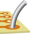
Figure 3-96
.
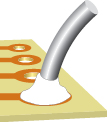
Figure 3-97
.
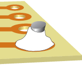
Figure 3-98.
To establish a connection between a section of wire and a copper trace on perforated board, the wire is pushed through the hole, and solder (shown in pure white for illustrative purposes) completes the connection. The wire can then be snipped short.
Allow enough solder to form a rounded bump sealing the wire and the copper, as shown in Figure 3-97. Wait for the solder to harden thoroughly, and then grab the wire with pointed-nosed pliers and wiggle it to make sure you have a strong connection. If all is well, snip the protruding wire with your cutters. See Figure 3-98.
Because solder joints are difficult to photograph, I’m using drawings to show the wire before and after making a reasonably good joint, which is shown in pure white, outlined with a black line.
Actual soldered perfboard is shown in the photographs in Figures 3-99 and 3-100.
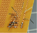
Figure 3-99.
This photograph was taken during the process of transferring components from breadboard to perforated board. Two or three components at a time are inserted from the other side of the board, and their leads are bent over to prevent them from falling out.
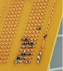
Figure 3-100.
After soldering, the leads are snipped short and the joints are inspected under a magnifying glass. Another two or three components can now be inserted, and the process can be repeated.